
Digital temperature sensing device using temperature depending characteristic of contact resistance

a temperature-dependent, digital technology, applied in the direction of heat measurement, instruments, material analysis, etc., can solve problems such as cost loss

Active Publication Date: 2006-06-29
SK HYNIX INC
View PDF10 Cites 33 Cited by
  • Summary
  • Abstract
  • Description
  • Claims
  • Application Information

AI Technical Summary

Benefits of technology

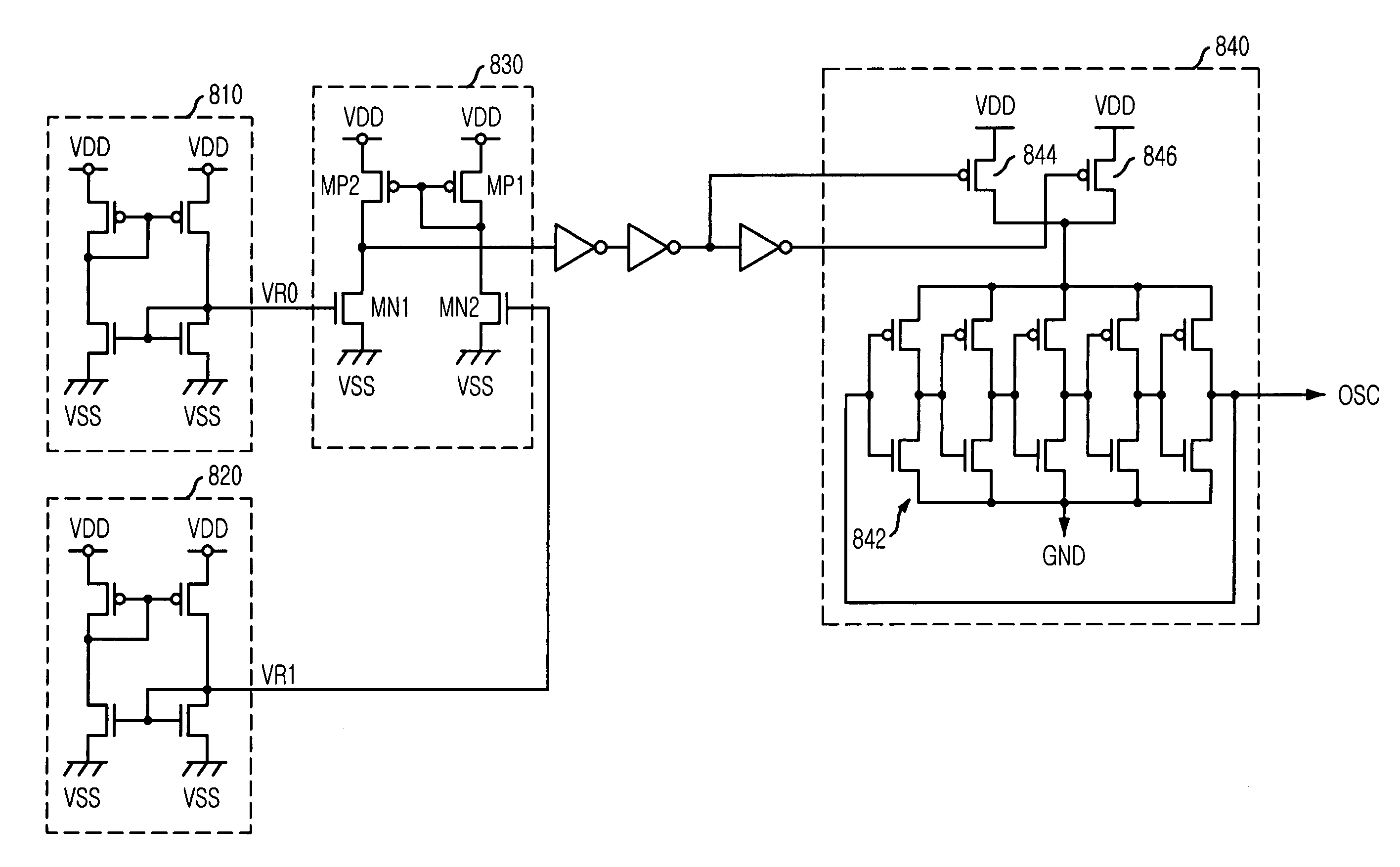
The present invention provides a digital temperature sensing device and a self-refresh driving device that adjusts the self-refresh period based on temperature. The device includes a first reference voltage generating unit that generates a reference voltage that is robust to temperature, using a plurality of MOS transistors with adjusted source contacts to compensate for variation in saturation current through source-drain. The device also includes a second reference voltage generating unit that generates a reference voltage that is sensitive to temperature, a level comparator that compares the first reference voltage with the second reference voltage, and an oscillator that generates clock signals with differing periods based on the output signal of the level comparator. The self-refresh driving device includes a first reference voltage generating unit, a second reference voltage generating unit, a level comparator, and an oscillator. The technical effects of the invention include improved accuracy and reliability of temperature sensing and adjustment of self-refresh period based on temperature, which can improve the performance and reliability of electronic devices.

Problems solved by technology

Accordingly, the failed integrated circuit is to be thrown, which leads producing cost loss.

Method used


Image

  • Digital temperature sensing device using temperature depending characteristic of contact resistance
  • Digital temperature sensing device using temperature depending characteristic of contact resistance
  • Digital temperature sensing device using temperature depending characteristic of contact resistance

Examples


Embodiment Construction

[0025] Hereinafter, a digital temperature sensing device and a self-refresh driving device using the same in accordance with the present invention will be described in detail referring to the accompanying drawings.

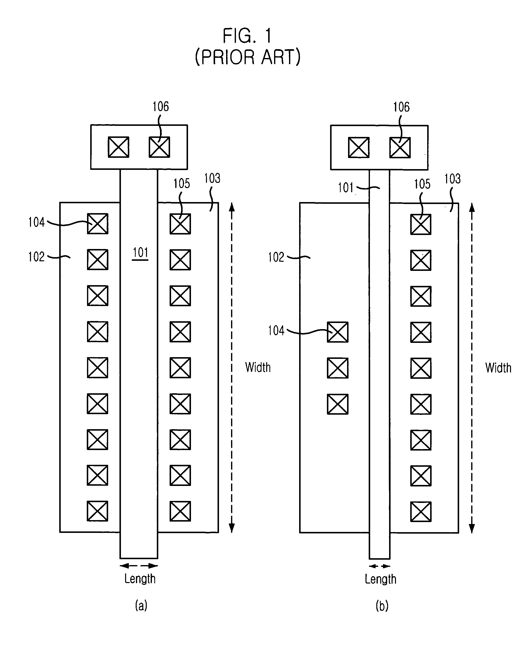
[0026]FIG. 1 shows layout diagrams of a conventional transistor and a transistor in accordance with the present invention.

[0027] Referring to layout diagrams (a) and (b) in FIG. 1, each of MOS transistors is constructed with a gate line 101, and a source region 102 and a drain region 103 arranged respectively besides the gate line 101. For the source 102 and the drain 103, contacts 104, 105 are formed for power input and internal connection between elements. Further, another contact 106 is formed at the gate 101.

[0028] The size of the transistor depends on width-to-length ratio of the gate.

[0029] Referring to FIG. 1, it can be seen that the number of contacts within the source region 102 of the MOS transistor of the present invention is fewer than the conventional MOS ...


PUM

PropertyMeasurementUnit
temperatureaaaaaaaaaa
power voltageaaaaaaaaaa

Abstract

A digital temperature sensing device uses temperature depending characteristic of contact resistance of a MOS transistor and a self-refresh driving device adjusts its self-refresh period depending on temperature using the digital temperature sensing device. The self-refresh driving device includes a first reference voltage generating unit for generating a reference voltage robust to temperature, the first reference voltage generating means being formed with a plurality of MOS transistors, the number of source contacts of the MOS transistors being adjusted such that variation of saturation current through source-drain is compensated for; a second reference voltage generating unit for generating a second reference voltage sensitive to temperature; a level comparator for comparing the first reference voltage with the second reference voltage; and an oscillator for generating a clock signals having differing period depending on the output signal of the level comparator.

Description

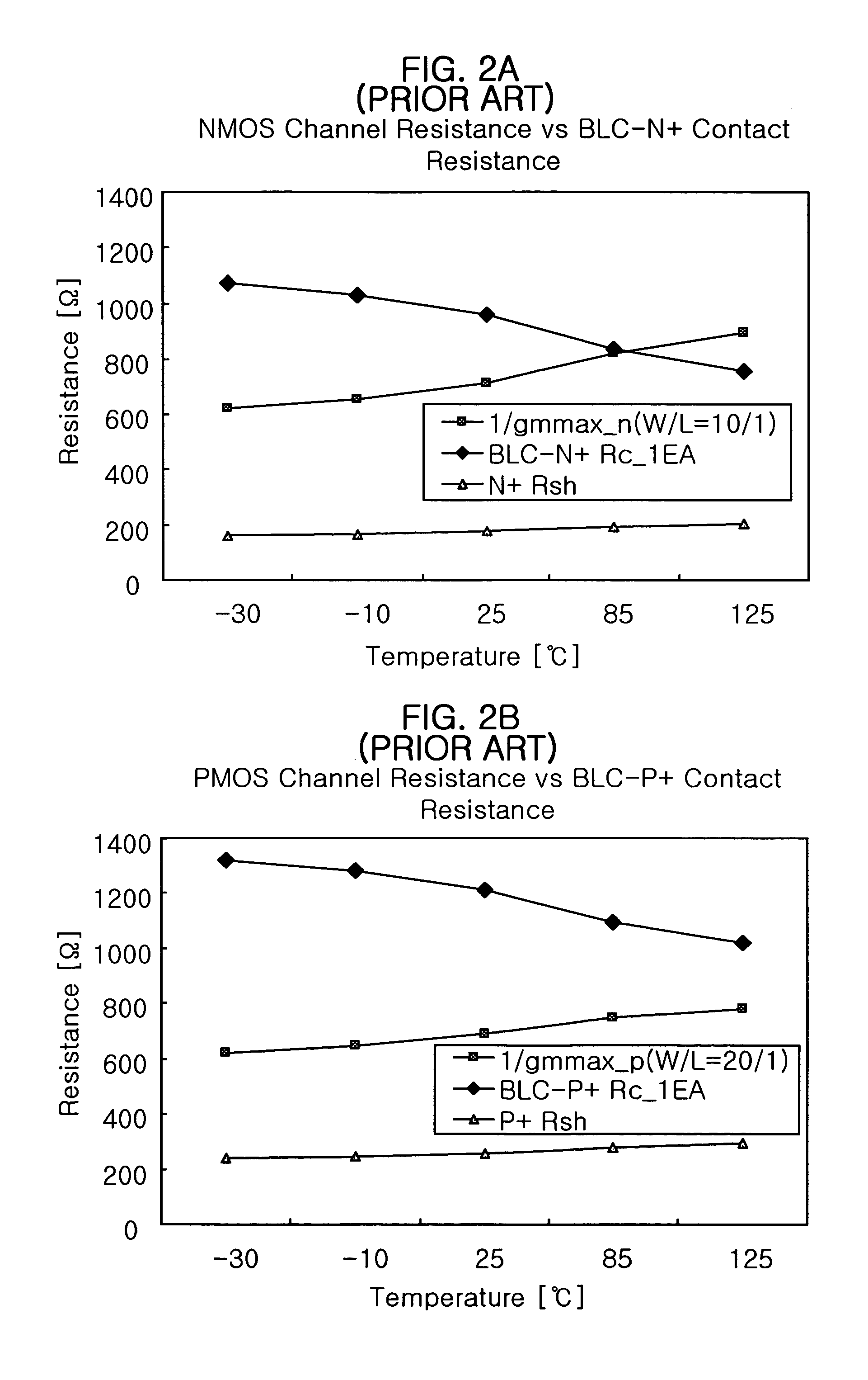
FIELD OF INVENTION [0001] The present invention relates to a semiconductor integrated circuit design; and, more particularly, to a digital temperature sensing device and a self-refresh driving device using the same. DESCRIPTION OF PRIOR ART [0002] As well known, a MOS transistor shows linear variation for saturation current through source-drain due to mobility characteristic depending on temperature. Accordingly, an integrated circuit (IC), such as a reference voltage source circuit, a delay circuit and so forth, that is designed with such a MOS transistor has characteristic variation due to the prescribed temperature depending characteristic. [0003] Therefore, integrated circuit suppliers test the integrated circuit under extreme condition such as −10° C. and 90° C. to screen the integrated circuit that satisfies all the specification. Accordingly, the failed integrated circuit is to be thrown, which leads producing cost loss. [0004] On the other hand, a DRAM performs self-refresh ...

Claims


Application Information

Patent Timeline
Patent Type & Authority Applications(United States)
IPC IPC(8): G01K7/00H01L31/058G01N27/04H10B12/00
CPCG01K7/01G01K7/226G11C11/40615G11C11/40626G11C11/4076
Inventor HAN, HI-HYUNCHOI, JUN-GI
Owner SK HYNIX INC
Learn More