Case for portable display devices

a display device and portable technology, applied in the field of multiinformation display devices, can solve the problems of deteriorating the display quality of the device, destroying the device by outer shock, etc., and achieve the effect of reducing the non-display area

Inactive Publication Date: 2006-06-29
KIM E E
View PDF27 Cites 20 Cited by
  • Summary
  • Abstract
  • Description
  • Claims
  • Application Information

AI Technical Summary

Benefits of technology

[0011] It is an objective of the present invention to provide a case for a portable display device that can minimize the non-display area by disposing adjacent display devices such that the adjacent walls of the display elements are arranged on an identical line when the device is unfolded and that can protect sidewalls of display elements, which are exposed outside when the device is folded,
[0012] It is another objective of the present invention to provide a fordable display device that is designed to cover adjacent portions of flat panel display elements that are exposed outside when the device is folded, thereby protecting the device from being damaged.
[0024] According to another embodiment of the present invention, the cover means is designed to be flexible and received in a shelter of the panel housing, the shelter receiving the cover means so that the cover means is not exposed outside when the panel housing is unfolded.
[0031] The cover means comprises a hinge shaft mounted on the first unit cover, the hinge shaft being inserted into a groove formed on the panel housing, the panel housing is provided with a hook portion for preventing the hinge shaft from moving away.
[0045] The cover means comprises a cover body for covering the opening of the panel housing and the sidewalls of the flat panel display elements and a mounting part formed on upper and lower portions of the cover body. And the cover means further comprises a guide wall enclosing the sidewall of the panel housing to prevent the panel housing from inadvertently unfolding.

Problems solved by technology

The non-display areas in the vicinity of the adjacent sidewalls make the screens of the display elements is seen to be divided, deteriorating the display quality of the device.
However, in the foldable information display, the flat display elements are closely arranged to reduce the non-display area when the device is unfolded, as a result of which the adjacent portions of the elements are exposed outside when the cases are folded on each other, thereby easily damaging the devices by outer shock.

Method used


Image

  • Case for portable display devices
  • Case for portable display devices
  • Case for portable display devices

Examples


first embodiment

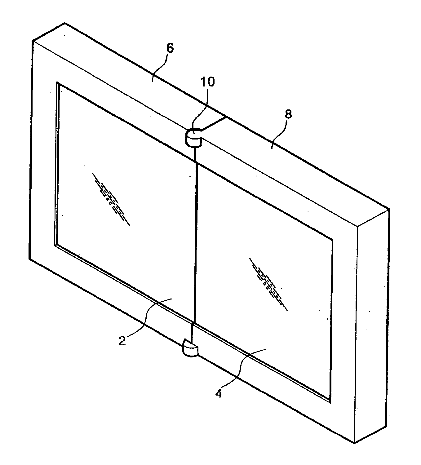
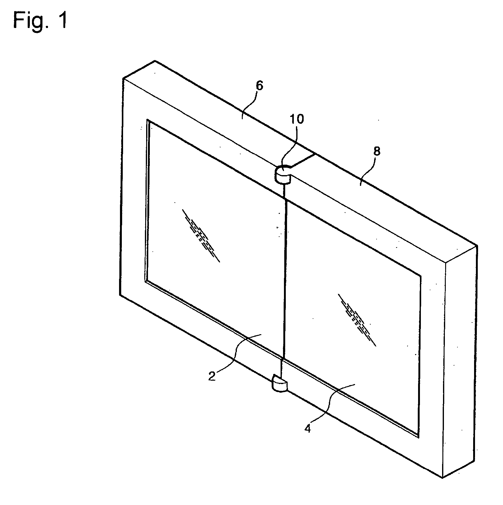
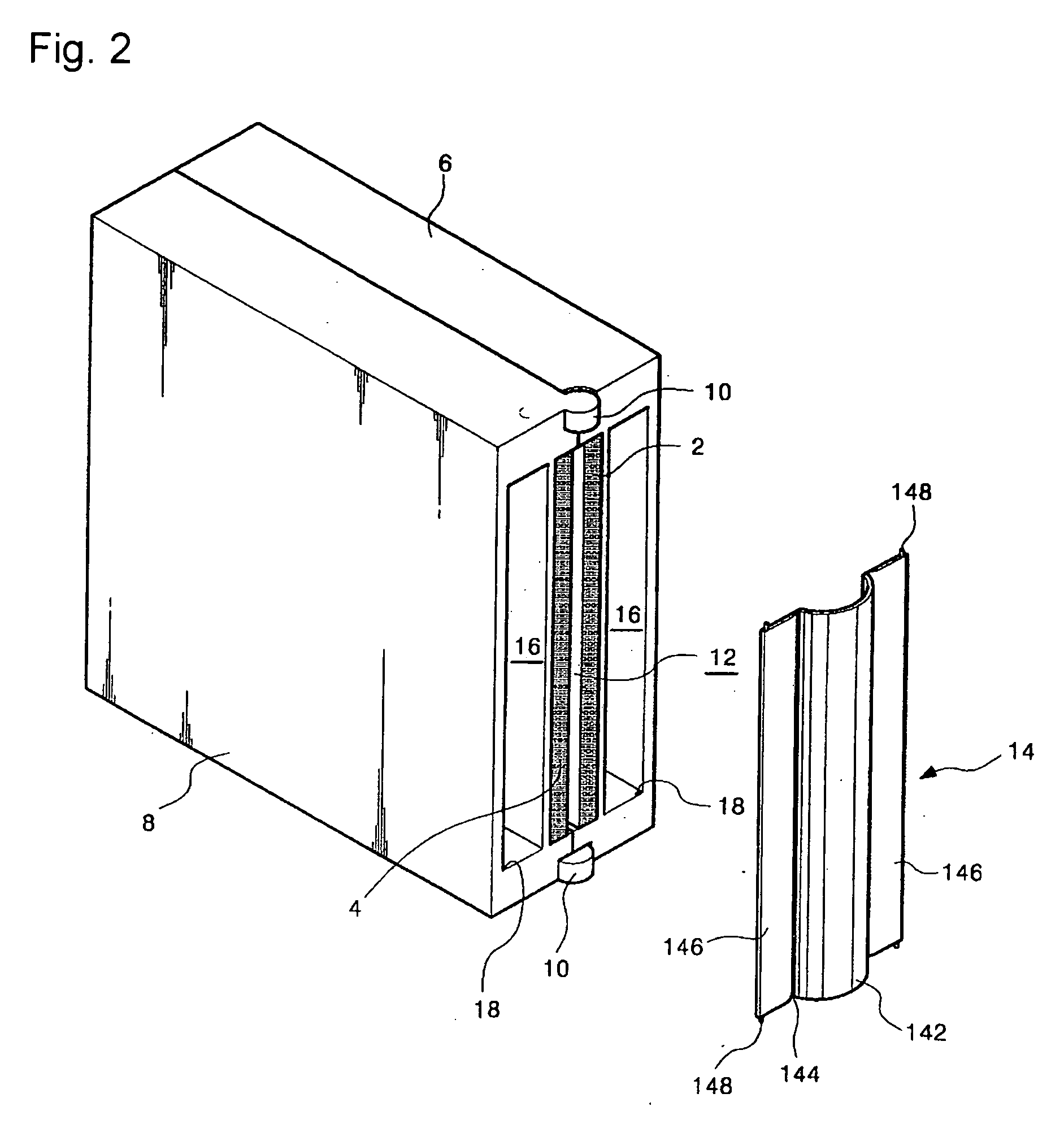
[0072] FIGS. 1 to 4 show a case for a portable display device according to a first embodiment of the present invention.

[0073] The inventive foldable case includes a pair of panel housings 6 and 8 for respectively receiving a pair flat display elements 2 and 4 and a folding support 10 for coupling the panel housings 6 and 8 such that the panel housings 6 and 8 can be folded on a same plane or at least 180°.

[0074] The flat display elements 2 and 4 are selected from the group consisting of an LCD, an FED, a PDP, and an EL including an organic EL.

[0075] The folding support 10 is preferably formed of a hinge assembly mounted on a border between the panel housings 6 and 8. The folding support 10 should be mounted on a rotational center of the panel housings 6 and 8 so that the adjacent sides of the flat panel elements 2 and 4 can be exactly located on the border between the flat panel elements 2 and 4.

[0076] In addition, to minimize the non-display area, the flat display elements 2 an...

second embodiment

[0103] FIGS. 10 to 12 show a case for a portable display device according to a second embodiment of the present invention.

[0104] The case includes a pair of panel housings 6 and 8 for respectively receiving a pair flat display elements 2 and 4 and a folding support 10′, and cover means 14.

[0105] The folding support 10′ is preferably formed of a hinge assembly mounted on a border between the panel housings 6 and 8. The folding support 10′ should be mounted on a rotational center of the panel housings 6 and 8 so that the adjacent sides of the flat panel elements 2 and 4 can be exactly located on the border between the flat panel elements 2 and 4.

[0106] In this embodiment, to cover the flat display elements 2 and 4 exposed through the opening 12, cover means is provided.

[0107] The cover means 14 preferably includes plural unit covers 158 connected to each other by a connecting portion 144. The connecting member 144 is defined by a thin part of the cover means 14 so that it can be f...

third embodiment

[0115] FIGS. 14 to 15 show a case for a portable display device according to a third embodiment of the present invention.

[0116] The case includes a pair of panel housings 6 and 8 for respectively receiving a pair flat display elements 2 and 4 and a folding support 10, and cover means 14.

[0117] In this embodiment, the cover means 14 for covering an opening12 of the panel housings 6 and 8 is designed to be extended when the panel housings 6 and 8 are folded and to be contracted when unfolded.

[0118] That is, the cover means 14 is formed in a bellows-shape. Describing more in detail, the cover means 14 comprises a coupling part 160 having coupling means fixed on an inner surface of the sidewall of the panel housings 6 and 8 and a bellows part 162.

[0119] The coupling part 160 includes a hole 160a and a screw (not shown) coupled in the hole 160a so as to be fixed on the inner surface of the panel housings 6 and 8.

[0120] The bellows part 162 is formed of fabric, plastic or synthetic r...


PUM


Abstract

The present invention is directed to a case for a portable display device that can realize a large-sized screen by interconnecting a plurality of display elements. When the display elements are unfolded, the adjacent sides of the display elements closely contact each other, thereby minimizing the non-display area. When the display elements are folded, the outer surface of the display elements can be protected. The case includes a foldable panel housing receiving at least two flat display panel elements. The panel housing is provided with an opening such that when the panel housing is unfolded, the adjacent sides of the flat display elements closes contact each other. The case further includes a hinge supporting member for providing the folding / unfolding operation of the panel housing and cover means for covering a side of the flat display elements, which is exposed through the opening, to protect the display elements.

Description

TECHNICAL FIELD [0001] The present invention relates to a multi-information display device that can realize the large-sized screen by connecting plural display elements, and more particularly to a fordable case for a portable display device that can minimize the non-display area by disposing adjacent display elements such that the adjacent walls of the display elements are arranged on an identical line when the device is unfolded and that can protect sidewalls of display elements, which are exposed outside when the device is folded. BACKGROUND ART [0002] In recent years, as the portable information device has been developed, it has been possible for a user to connect to the network and to computing-work using a portable computer, a digital portable communication device and other periphery devices regardless of where the user is. [0003] Accordingly, the use of the portable information devices is gradually increased. Therefore, it is required to reduce the size, weight, thickness of a...

Claims


Application Information

Patent Timeline
Patent Type & Authority Applications(United States)
IPC IPC(8): A47B81/00A47B97/00F16C11/10F16C11/04G06F1/16G09F9/00G09F9/30G09F9/40H04M1/02
CPCG06F1/1601G06F1/1616G06F1/1637G06F1/1641G06F1/1681G06F2200/1612G09F9/30
Inventor KIM, SI HANKIM, JANG HOKIM, HYUNG NYUN
Owner KIM E E
Why Eureka
Try Eureka