Apparatus for driving cold cathode fluorescent lamps

Inactive Publication Date: 2006-06-29
GOLD CHARM LTD
View PDF6 Cites 6 Cited by
  • Summary
  • Abstract
  • Description
  • Claims
  • Application Information

AI Technical Summary

Benefits of technology

[0009] An apparatus for driving Cold Cathode Fluorescent Lamps (CCFL) includes: a buck converter connected to a direct-current power supply; a resonant boost converter connected to the buck converter; one or more CCFLs connected to the resonant boost converter; and a starting voltage adjustment circuit connected between the buck converter and the resonant boost converter, for adjusting the starting voltage applied to the CCFLs according to the temperature of the environment within which they ar

Problems solved by technology

Fluorescent lamps are used in a number of applications where light is required but the power required to generate light is limited.
However, high starting voltages can seriously shorten the life span of CCFLs.

Method used


Image

  • Apparatus for driving cold cathode fluorescent lamps
  • Apparatus for driving cold cathode fluorescent lamps
  • Apparatus for driving cold cathode fluorescent lamps

Examples


Embodiment Construction

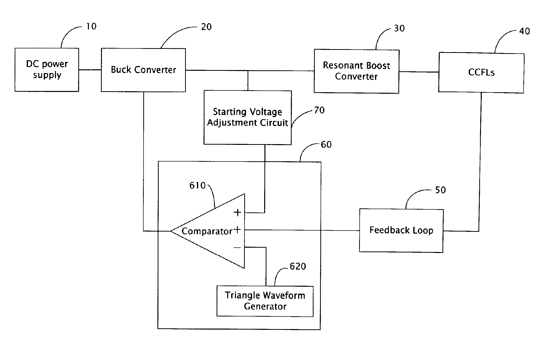
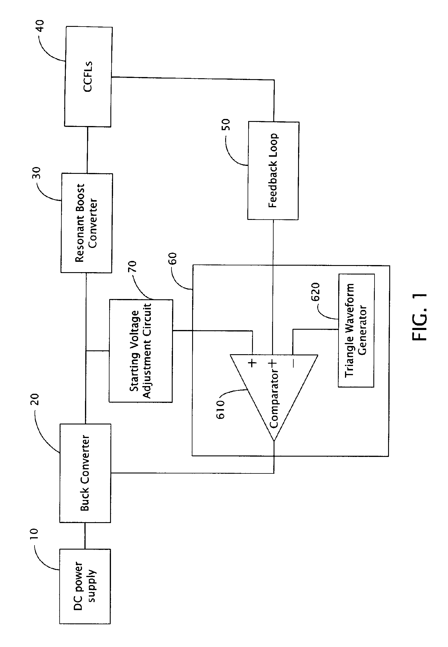
[0015]FIG. 1 is a block diagram of an apparatus for driving Cold Cathode Fluorescent Lamps (CCFLs) (hereinafter, “the apparatus”) according to a preferred embodiment of the present invention. The apparatus includes a buck converter 20, and a resonant boost converter 30 connected to the buck converter 20. The buck converter 20 receives power from a DC power supply 10, and transfers the power to one or more CCFLs 40 via the resonant boost converter 30. A feedback loop 50 and a PWM (pulse-width modulation) control circuit 60 are positioned sequentially between the CCFLs 40 and the buck converter 20. The PWM control circuit 60 includes a modulation signal generator and a comparator 610. In FIG. 1, the modulation signal generator is detailed as a triangle waveform generator 620. However, the modulation signal generator can be provided in any other suitable form, such as a saw-tooth waveform generator, or even a trapezoidal waveform generator. The comparator 610 includes a plurality of in...


PUM


Abstract

A starting voltage adjustment circuit (70), which can vary starting voltages to CCFLs (40) according to variations in the temperature of the immediate environment, is employed in an apparatus for driving CCFLs. The starting voltage adjustment circuit includes a zener diode (710), a thermal resistor (720), and a voltage dividing resistor (730) connected in series between a buck converter, a resonant boost converter, and ground. The starting voltage adjustment circuit also includes a control chip (740) which includes pins, of which one is connected between the thermal resistor and the voltage dividing resistor and outputs a constant voltage, and another is connected between the voltage dividing resistor and ground. The thermal resistor has a voltage drop thereacross varying with the temperature. The starting voltage adjustment circuit adjusts an input voltage to the resonant boost converter, thereby adjusting the starting voltage to the CCFLs according to variations in temperature.

Description

DESCRIPTION [0001] 1. Field of the Invention [0002] The present invention relates to an apparatus for driving lamps, and particularly to an apparatus for driving Cold Cathode Fluorescent Lamps (CCFLs). [0003] 2. Description of Related Art [0004] Fluorescent lamps are used in a number of applications where light is required but the power required to generate light is limited. One particular type of fluorescent lamp is the Cold Cathode Fluorescent Lamp (CCFL) which provides illumination in a variety of electronic devices, such as flat panel displays, computers, personal digital assistants, scanners, facsimile machines, copiers, and the like. [0005] CCFL tubes typically contain a gas, such as Argon, Xenon, or the like, along with a small amount of Mercury. CCFLs require a high starting voltage, generally from 700-1,700 volts, for a short time at an initial ignition stage to ionize the gas contained within the CCFL tubes and ignite the CCFLs. After the gas in the CCFLs is ionized and th...

Claims


Application Information

Patent Timeline
IPC IPC(8): H05B37/02
CPCH05B41/282H05B41/382H05B41/386
Inventor HSIEH, KUAN-HONGBAO, WEI-DE
Owner GOLD CHARM LTD
Why Eureka
Try Eureka