Apparatus and method to improve quality of moving image displayed on liquid crystal display device

a liquid crystal display and moving image technology, applied in the direction of optics, identification means, instruments, etc., can solve the problems of increasing circuit size, flickering, and blurring (image tailing) of moving images, so as to prevent uneven brightness

Inactive Publication Date: 2006-06-29
SHARP KK
View PDF12 Cites 83 Cited by
  • Summary
  • Abstract
  • Description
  • Claims
  • Application Information

AI Technical Summary

Benefits of technology

[0132] According to another aspect of the liquid crystal display device controlling method in the present invention, reset data are also written in a blanking period. Therefore, the reset data are always written after a certain amount of time has elapsed since display data writing. As a result, in each pixel electrode, display data are displayed for the same duration and a period of displaying the reset data becomes equal. Therefore, brightness of the display data in the panel can be uniformed and brightness can be prevented from becoming uneven.

Problems solved by technology

As a result, blurring (image tailing) occurs in a moving image due to partial overlap of display data in a previous frame.
However, line-sequential writing of the display data (white) and the reset data (black) in alternation causes flicker.
Especially, when a display speed of the liquid crystal cells C is low, or when a scanning period (refresh rate) is long, flicker becomes large.
However, liquid crystal display devices of this kind have the plurality of X drivers and Y drivers, which leads an increase in circuit size.
Furthermore, since the number of signal lines becomes double, a problem of aperture ratio reduction also occurs.
As a result, a problem of wasteful power consumption occurs.
As a result, power consumption increases.
In the case where a plurality of fluorescent tubes laid out in parallel are used as the backlight, a problem of uneven image display caused by a difference in a degradation speed of each fluorescent tube also occurs.

Method used


Image

  • Apparatus and method to improve quality of moving image displayed on liquid crystal display device
  • Apparatus and method to improve quality of moving image displayed on liquid crystal display device
  • Apparatus and method to improve quality of moving image displayed on liquid crystal display device

Examples


first embodiment

the Liquid Crystal Display Device and the First Embodiment of the Liquid Crystal Display Device Controlling Method

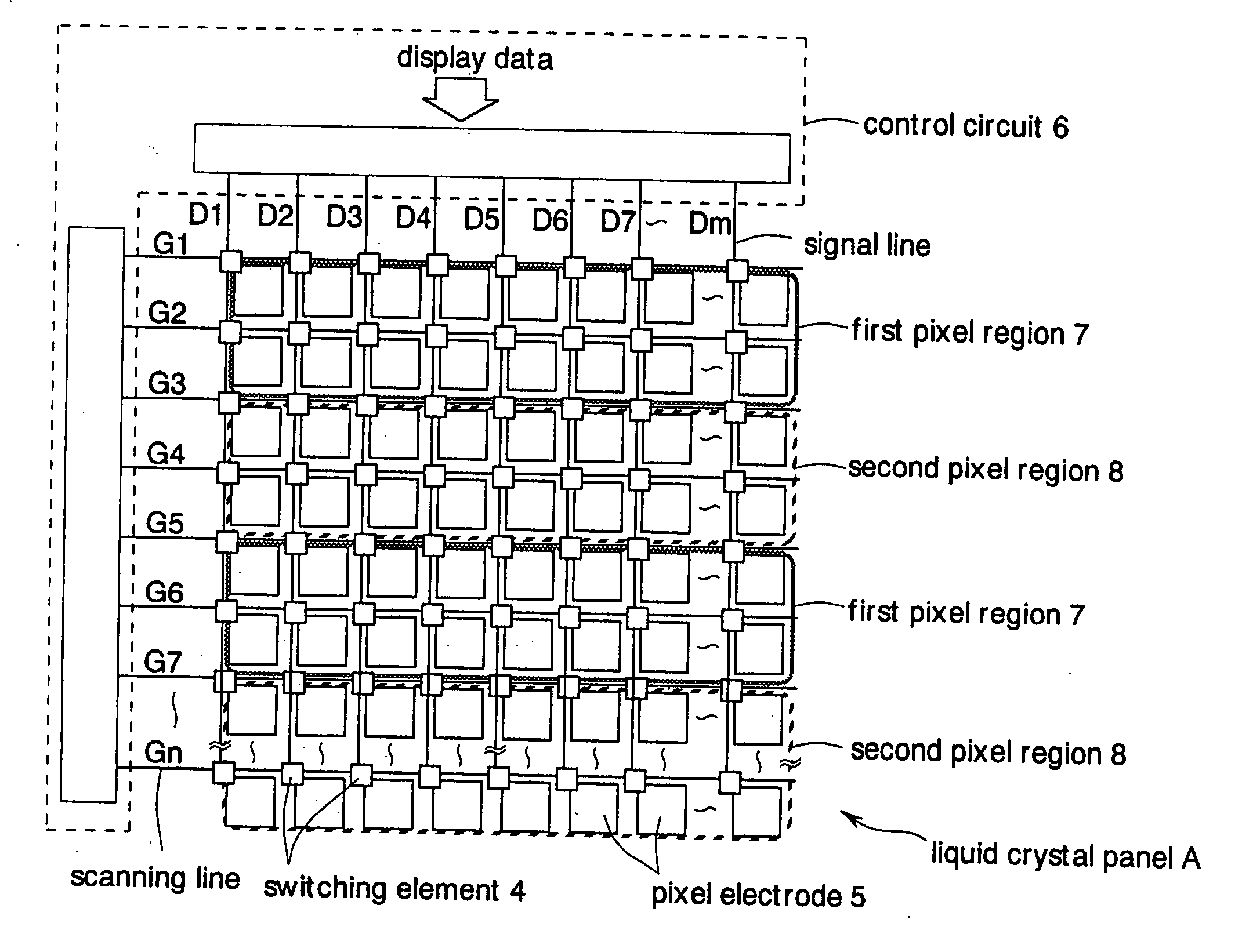
[0225]FIG. 9 shows an outline of a TFT (Thin Film Transistor) driving liquid crystal display device used in this embodiment.

[0226] This device comprises TFTs and pixel electrodes 12 laid out in the form of a matrix. Gate electrodes of the TFTs which are switching elements are connected to the scanning lines G1-Gn. The scanning lines G1-Gn are lines for transmitting gate signals output from a Y driver 14. Drain electrodes of the TFTs are connected to the signal lines D1-Dm. The signal lines D1-Dm are signal lines for transmitting data signals from an X driver 16. The source electrodes of the TFTs are connected to the pixel electrodes 12.

[0227] Counter electrodes (not shown) are arranged, facing the pixel electrodes 12. Liquid crystals (not shown) are sandwiched by the pixel electrodes 12 and the counter electrodes, forming liquid crystal cells C. The liquid crystal pane...

second embodiment

the Liquid Crystal Display Device and the Second Embodiment of the Liquid Crystal Display Device Controlling Method

[0243] In this embodiment, elements corresponding to the elements described above for the first embodiment are given the same reference numerals and explanation of these elements is not repeated.

[0244]FIG. 11 shows an outline of the TFT (Thin Film Transistor) driving liquid crystal display device used in this embodiment. In this embodiment, the first pixel regions 20 and the second pixel regions 22 are in a lattice-like form of each liquid crystal cell C. A control circuit 24 comprises a buffer memory 24a for retaining a portion of the display data transmitted from exterior. Other configurations are the same as in the first embodiment.

[0245]FIG. 12 shows a state in which display data are written in the liquid crystal display device described above.

[0246] In this embodiment, the control circuit 24 shown in FIG. 11 receives display data for one image in one frame perio...

third embodiment

the Liquid Crystal Display Device and the Third Embodiment of the Liquid Crystal Display Device Controlling Method

[0254]FIG. 13 shows a configuration of the TFT (Thin Film Transistor) driving liquid crystal display device used in this embodiment. In this embodiment, elements corresponding to the elements described above in the first embodiment are given the same reference numerals and explanation of these elements is not repeated.

[0255] In this embodiment, the liquid crystal panel A comprises the two first pixel regions 20 and the two second pixel regions 22 arranged alternately in the form of stripes.

[0256] Each of the first pixel regions 20 and the second pixel regions 22 is divided according to liquid crystal cells C corresponding to two scanning lines. The liquid crystal panel A is assumed to have 8 pixels in vertical direction and 8 pixels in horizontal direction, for the sake of simpler explanation. In reality, the height and the width of the liquid crystal cells C are appro...


PUM

PropertyMeasurementUnit
voltageaaaaaaaaaa
voltageaaaaaaaaaa
response timeaaaaaaaaaa

Abstract

A liquid crystal display device includes a panel having pixel electrodes arranged at intersections of a plurality of signal lines via switching elements for transmitting display data and a plurality of scanning lines for transmitting control signals, and a control circuit for controlling the panel. The liquid crystal panel is divided into first pixel regions and second pixel regions adjacent to the first pixel regions. The control circuit carries out impulse driving in which the control signals transmitted to each of the scanning lines are activated two times in one frame period for displaying an image. The control circuit writes the display data in either one of the pixel regions and writes reset data in the other pixel regions when the control signals are activated once of the two times. By writing the reset data in the pixel regions, the display data written in an immediately preceding frame are reset. In consecutive frames, the display data written in the pixel regions are always reset in one frame period. Therefore, blurring in a moving image can be alleviated. Since writing the display data and the reset data is carried out separately in the first pixel regions and in the second pixel regions, flicker is prevented from occurring in a display screen.

Description

[0001] This is divisional of application Ser. No. 09 / 651,288, filed Aug. 30, 2000.BACKGROUND OF THE INVENTION [0002] 1. Field of the Invention [0003] The present invention relates to a liquid crystal display device of active matrix type and a method of controlling the liquid crystal display device. Especially, the present invention relates to a technique for preferable image display. [0004] 2. Description of the Related Art [0005] Liquid crystal display devices of active matrix type using TFTs (Thin Film Transistors) as driving elements have been in wide use as display devices for personal computers or the like. Generally, liquid crystal devices of this kind often adopt a display method called a TN (Twisted Nematic) type. A liquid crystal display device of TN type are formed with twisted nematic cells in which arrangement of liquid crystal molecules are consecutively twisted by 90 degrees, with the liquid crystal cells sandwiched between two transparent electrode-plated substrates. ...

Claims


Application Information

Patent Timeline
Patent Type & Authority Applications(United States)
IPC IPC(8): G09G3/36G02F1/13363G02F1/133G02F1/1335G02F1/13357G02F1/136G02F1/1368G09F9/00G09F9/30G09G3/20G09G3/34
CPCG09G3/342G09G3/3648G09G3/3666G09G2310/024G09G2310/04G09G2310/062G09G2310/063G09G2320/0233G09G2320/0238G09G2320/0247G09G2320/0261G09G2330/021G02F1/136
Inventor YOSHIDA, HIDEFUMITANUMA, SEIJIMAYAMA, TAKATOSHIINOUE, YUICHISUZUKI, TOSHIAKIHANAOKA, KAZUTAKAGOTOH, TAKESHIKOBAYASHI, TETSUYAOHASHI, MAKOTOYAMAGUCHI, HISASHITANAKA, KATSUNORIKATAGAWA, KOICHI
Owner SHARP KK
Why Eureka
Try Eureka