

Method for detecting interlaced material and field order
a material detection and interlaced technology, applied in the field of video data processing methods and apparatuses, can solve the problems of inability to determine whether the streamed material is progressive or interlaced, difficult to best display interlaced material on progressive scan displays or vice-versa, and severe visual artifacts can occur especially for high motion scenes
- Summary
- Abstract
- Description
- Claims
- Application Information
AI Technical Summary
Benefits of technology
Problems solved by technology
Method used
Image

Examples
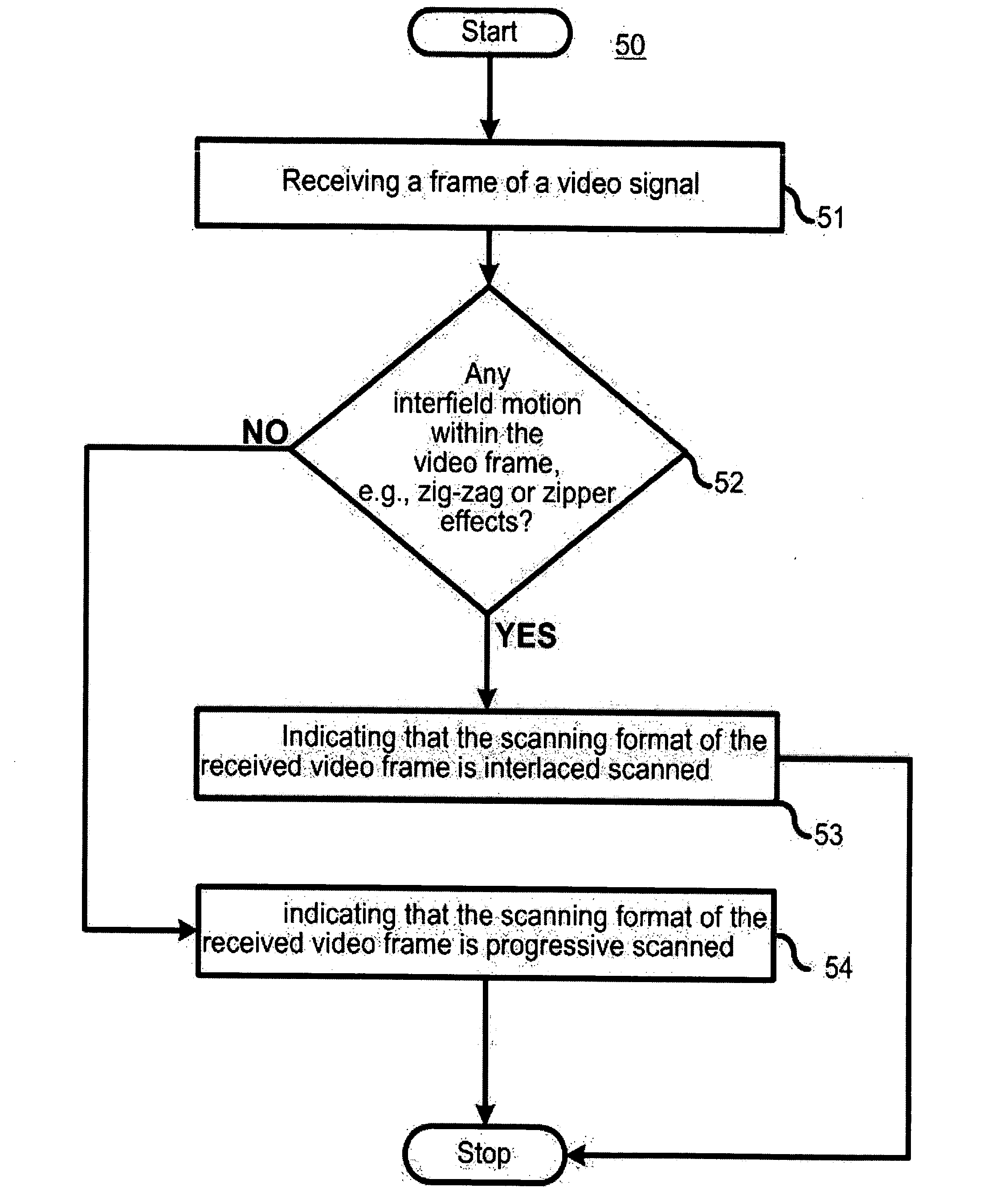
exemplary embodiment 50
[0034] Turning to FIG. 5, shown therein is an exemplary embodiment 50 of a method for determining a scanning format of a frame of a video signal. According to one aspect of the present invention, the exemplary embodiment 50 of the method for determining whether a given frame is progressive or interlaced detects whether or not there is any interfield motion. Thus, in element 51, the exemplary embodiment 50 receives a frame of the video signal, and in element 52 then first determines whether any interfield motion exists. The presence of such interfield motion indicates that the frame was probably interlaced scanned, whereas the absence probably indicates that the frame was progressive scanned. Thus, in element 53, the exemplary embodiment indicates that the received frame was interlaced scanned as interfield motion was detected in element 52, whereas in element 54 the exemplary embodiment indicates that the received frame was progressive scanned as no interfield motion was detected in...
exemplary embodiment 60
[0037] Turning to FIG. 6, shown therein is another exemplary embodiment 60 of a method for determining the scanning format of a frame of a video signal. According to this exemplary embodiment 60, to determine if the frame was interlace scanned, the exemplary embodiment: (1) looks for vertical edges by performing standard vertical edge detection within a field (intrafield), such as using gradient-based methods; and then: (2) checks in the vertical edge regions as to whether there are any vertical zippers in the corresponding frame. A frame with a significant amount of vertical zippers would be viewed as an interlaced frame; otherwise, the frame would be detected as progressive.
[0038] Thus, a frame of a video signal is received in element 61. Next, in element 62, the exemplary embodiment 60 then performs edge detection to detect one or more vertical edges within a field (intrafield) of the video frame. The exemplary embodiment 60 then determines whether a significant amount of vertica...
exemplary embodiment 80
[0066] With a motion analysis approach, performance is expected to improve with more frames of data and with high motion. Correct detection is difficult for low motion sequences, but in these cases the consequences of an incorrect decision may be small. In general, more than one frame of data is needed for detection, since a single frame contains only one time instance of each field. Turning to FIG. 8, shown therein is an exemplary embodiment 80 for determining field order that uses at least two frames of data to perform detection, and is based upon the interlace detection approach described above. Note that field order detection can be determined for individual frames or for a group of frames. If it is assumed that a given video sequence is known to be consistently either top field first or bottom field first within the sequence, then the detection will generally be more reliable when performed over more frames.
[0067] Consider two consecutive frames—curr(0) and next(1)—and their re...
PUM
 Abstract
Description
Claims
Application Information