Method for treating a screw-cement retained prosthesis, abutment and implant for a screw-cement retained prosthesis

a technology of screw-cement and retained prosthesis, which is applied in the field of dental implants, can solve the problems of difficult repair of the prosthetic appliance, high cost and long time, and difficulty in achieving a precise passive fit, and achieve the effect of precise clinical and laboratory procedures, long time, and high cos

Inactive Publication Date: 2006-06-29
HEO YOUNG KU
View PDF13 Cites 33 Cited by
  • Summary
  • Abstract
  • Description
  • Claims
  • Application Information

AI Technical Summary

Benefits of technology

[0049] As described above, advantages and disadvantages of the screw retained prosthesis and the cement retained prosthesis are summarized as follows. The screw retained prosthesis has the advantages that the prosthetic appliance is freely mounted and separated, and the treatment can be performed even with a short intermaxillary distance. However, there are some disadvantages that it is difficult to achieve a precise passive fit, the screw often comes loose, precise clinical and laboratory procedures are required, and a high cost and a long time are required.

Problems solved by technology

However, there are some disadvantages that it is difficult to achieve a precise passive fit, the screw often comes loose, precise clinical and laboratory procedures are required, and a high cost and a long time are required.
However, since the prosthetic appliance cannot be easily separated once the prosthetic appliance and the abutment are bonded, there are some disadvantages that repairs of the prosthetic appliance are difficult, removing the remaining cement in the oral cavity is also difficult, and polishing a border cannot be performed even if the border of the prosthetic appliance is unfit.

Method used


Image

  • Method for treating a screw-cement retained prosthesis, abutment and implant for a screw-cement retained prosthesis
  • Method for treating a screw-cement retained prosthesis, abutment and implant for a screw-cement retained prosthesis
  • Method for treating a screw-cement retained prosthesis, abutment and implant for a screw-cement retained prosthesis

Examples


embodiment 1

[0095]FIG. 4 is a sectional view of an SCRP implant according to Embodiment 1 of the present invention, and FIGS. 5a to 5e are sectional views for explaining a method for treating the SCRP implant according to Embodiment 1.

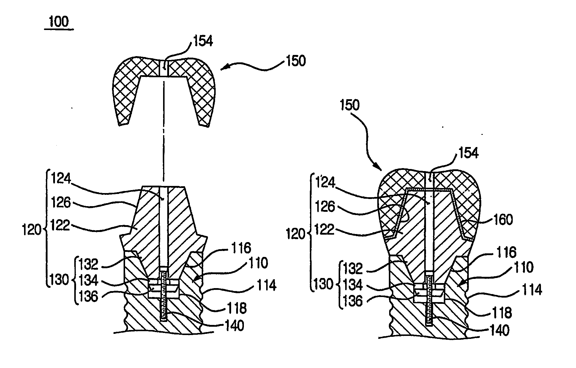
[0096] Referring to FIG. 4, the SCRP implant 100 according to Embodiment 1 comprises a fixture 110, an abutment 120, a screw 140 and a prosthetic appliance 150.

[0097] The fixture 110 comprises the thread 114 formed in its outer surface and is implanted along the thread 114 to the alveolar bone. The thread 114 of the implanted fixture 110 is fused with tissue of the alveolar bone and then is fixed to the alveolar bone. Generally, considerable time is needed for bonding the thread 114 and the alveolar bone to each other.

[0098] A joining groove 112 for receiving a joining projection 130 of the abutment 120 is formed on an upper surface of the fixture 110. The joining groove 112 has a circular inlet, and comprises a sticking groove 116 in a truncated circular conic...

embodiment 2

[0118]FIG. 6 is a sectional view of an SCRP implant according to Embodiment 2 of the present invention, and FIG. 7 is a sectional view for explaining a separating process of the SCRP implant according to Embodiment 2.

[0119] Referring to FIG. 6, the SCRP implant according to Embodiment 2 comprises the fixture 110, an abutment 220, the screw 140 and the prosthetic appliance 150. The fixture 110, screw 140 and prosthetic appliance 150 except the abutment 220 may refer to the explanations and drawings of Embodiment 1, and repetitional contents may be omitted.

[0120] The fixture 110 comprises the joining groove 112 and the thread 114, wherein the joining groove 112 comprises the truncated circular conical sticking groove 116 and the anti-rotating groove 118. A female screw hole corresponding to the screw 140 is formed at the center of the lower end of the anti-rotating groove 118.

[0121] In the same manner as Embodiment 1, the abutment 220 according to the present embodiment comprises a...

embodiment 3

[0129]FIG. 8 is a sectional view of an SCRP implant according to Embodiment 3 of the present invention, and FIG. 9 is a sectional view for explaining a separating process of the SCRP implant according to Embodiment 3.

[0130] Referring to FIG. 8, the SCRP implant according to Embodiment 3 comprises the fixture 110, an abutment 320, the screw 140 and the prosthetic appliance 150. The fixture 110, screw 140 and prosthetic appliance 150 except the abutment 320 may refer to the explanations and drawings of Embodiment 1, and repetitional contents may be omitted.

[0131] The fixture 110 comprises the joining groove 112 and the thread 114, wherein the joining groove 112 comprises the truncated circular conical sticking groove 116 and the anti-rotating groove 118. A female screw hole corresponding to the screw 140 is formed at the center of the lower end of the anti-rotating groove 118.

[0132] In the same manner as Embodiment 1, the abutment 320 according to the present embodiment comprises a...


PUM


Abstract

A method for treating a screw-cement retained prosthesis, an abutment and an implant are disclosed. The method for treating the screw-cement retained prosthesis, which relates to an internal implant, comprises the steps of providing an abutment comprising a joining projection, repositioning the joining projection to a joining groove formed in the upper portion of a fixture, engaging the abutment to the fixture by using a screw, providing a prosthetic appliance including a screw hole, and bonding the prosthetic appliance and the abutment by interposing dental cement between the abutment and the prosthetic appliance. The present invention includes all of the advantages of screw retained prostheses and cement retained prostheses and at the same time can solve the disadvantages thereof. Using a leading inclined surface formed in the joining projection, the abutment and prosthetic appliance are easily separated from and remounted to the fixture.

Description

TECHNICAL FIELD [0001] The present invention relates to a dental implant, and more particularly to a method for treating an internal implant wherein it is simple to treat and easy to assemble and disassemble the implant and an abutment and an internal implant for a screw-cement retained prosthesis which is employed in the above treatment method. BACKGROUND ART [0002] A dental implant means a dental treating method or an artificial tooth structure that is formed by implanting an artificial dental root in a region where a tooth has been partially or wholly lost, causing the artificial dental root to adhere to an alveolar bone, and fixing a prosthesis or crown to the artificial dental root. Generally, the implant comprises a titanium fixture, an abutment fixed onto the fixture, an abutment screw for fixing the abutment to the fixture, and a prosthesis as an artificial tooth secured to the abutment. [0003] The implant makes it possible to treat only an injured portion without injuring a...

Claims


Application Information

Patent Timeline
Patent Type & Authority Applications(United States)
IPC IPC(8): A61C8/00
CPCA61C8/0048A61C8/005A61C8/0054A61C8/006A61C8/0069A61C8/0068
Inventor HEO, YOUNG KU
Owner HEO YOUNG KU
Why Eureka
Try Eureka