

Electrical connector with provisions to reduce thermally-induced stresses
- Summary
- Abstract
- Description
- Claims
- Application Information
AI Technical Summary
Benefits of technology
Problems solved by technology
Method used
Image

Examples
Embodiment Construction
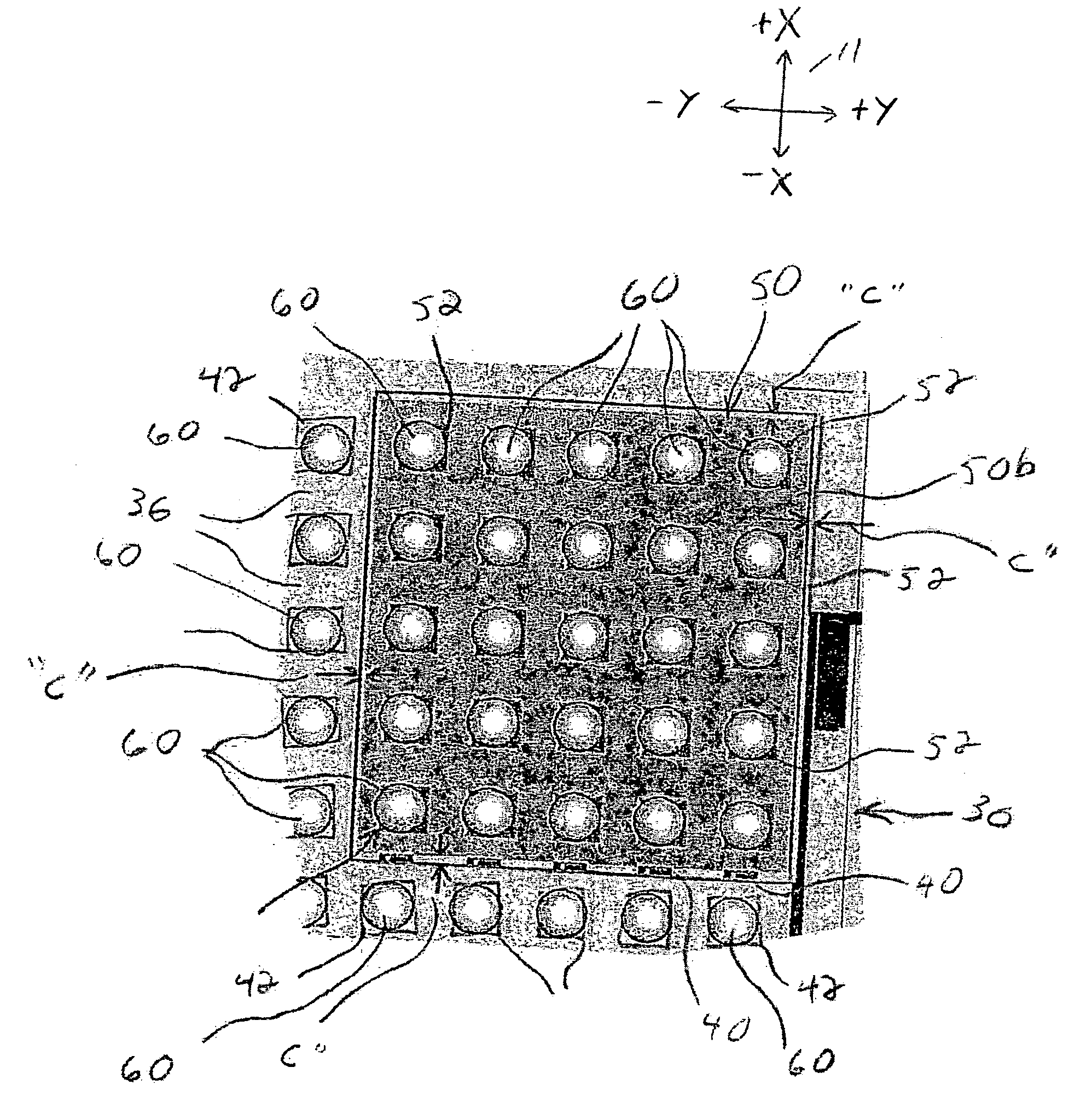
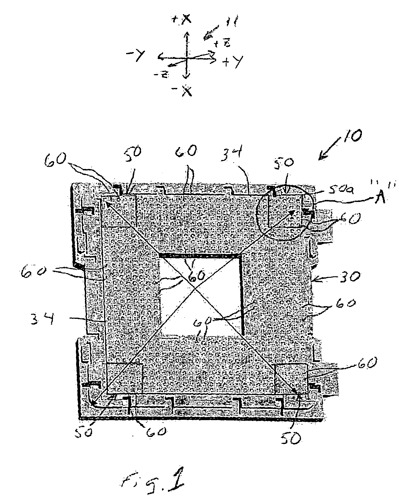
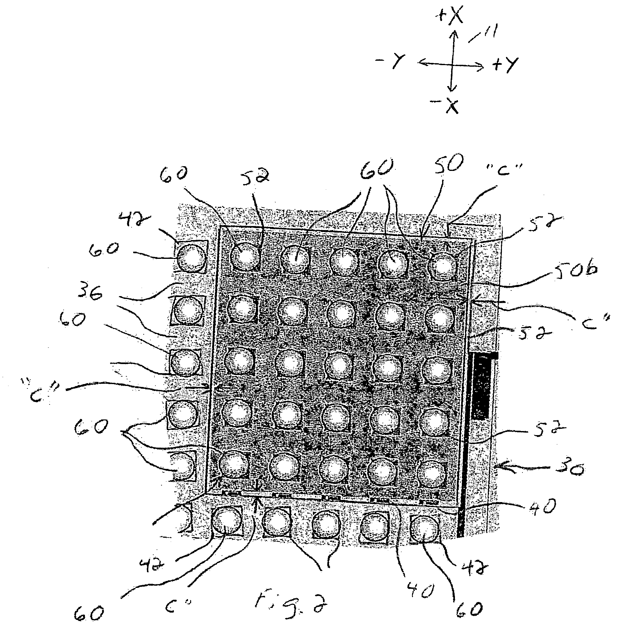
[0030]FIGS. 1-9 depict a preferred embodiment of an electrical connector 10. The figures are each referenced to a common coordinate system 11 depicted therein. The connector 10 is a socket for a BGA connector. This particular type of connector is disclosed for exemplary purposes only, as the principles of the present invention can be applied to other types of connectors.
[0031] The connector 10 can be mounted on a substrate 12 (see FIG. 9). The substrate 12 can be, for example, a printed circuit board, a printed wire board, a backplane, etc.
[0032] The connector 10 comprises a housing 14. The housing 14 is formed from a suitable electrically-insulative material such as plastic.
[0033] The connector 10 also comprises a plurality of contacts 18a, 18b mounted on the housing 14. (The contacts 18a are substantially identical to the contacts 18b; different reference symbols are used to denote differences between the respective positions of the contacts 18a, 18b within the housing 14, as d...
PUM
 Abstract
Description
Claims
Application Information