Rod cradle, instert to be used in a rod cradle, and method for inserting a rod in a rod cradle

a technology of rod cradle and rod cradle, which is applied in the direction of superimposed coating process, liquid/solution decomposition chemical coating, manufacturing tools, etc., can solve the problems of inability to meet the requirements of production, so as to improve the retention simple and reliable operation, and ensure the effect of insert and rod in the groov

Active Publication Date: 2011-10-04
VALMET TECH INC
View PDF11 Cites 3 Cited by
  • Summary
  • Abstract
  • Description
  • Claims
  • Application Information

AI Technical Summary

Benefits of technology

[0008]The invention is intended to create a new type of rod cradle, in which the retention of the insert and the rod in the grooves is ensured better than previously. The invention is also intended to create a new type of insert for use in a rod cradle, which will ensure the retention of the insert and rod better than previously. In addition, the invention is intended to create a new type of method for setting a rod in a rod cradle. The invention includes both a rod-cradle frame and an insert, which is locked to the frame using the rod placed in the rod groove, i.e. the insert is locked when the rod is placed in the rod groove in the insert. When the rod locks the insert in the frame profile, the construction of the rod cradle is simpler and more reliable in operation than previously.
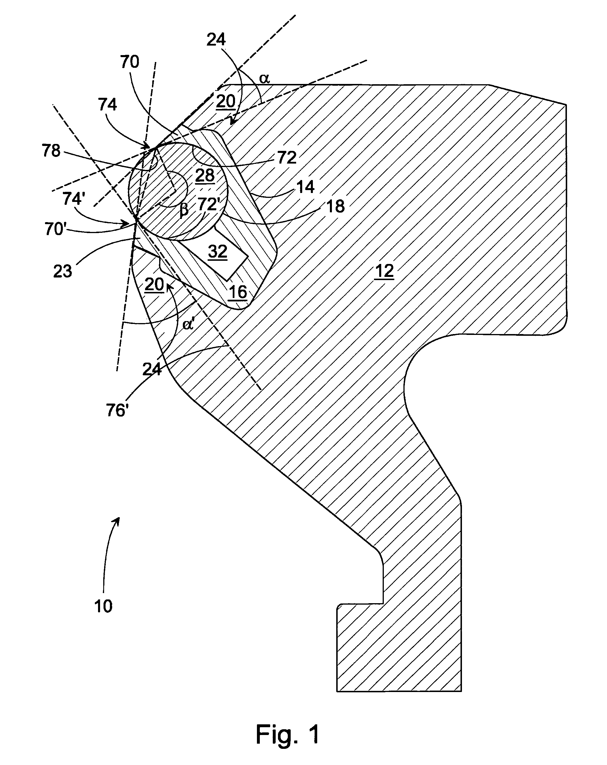
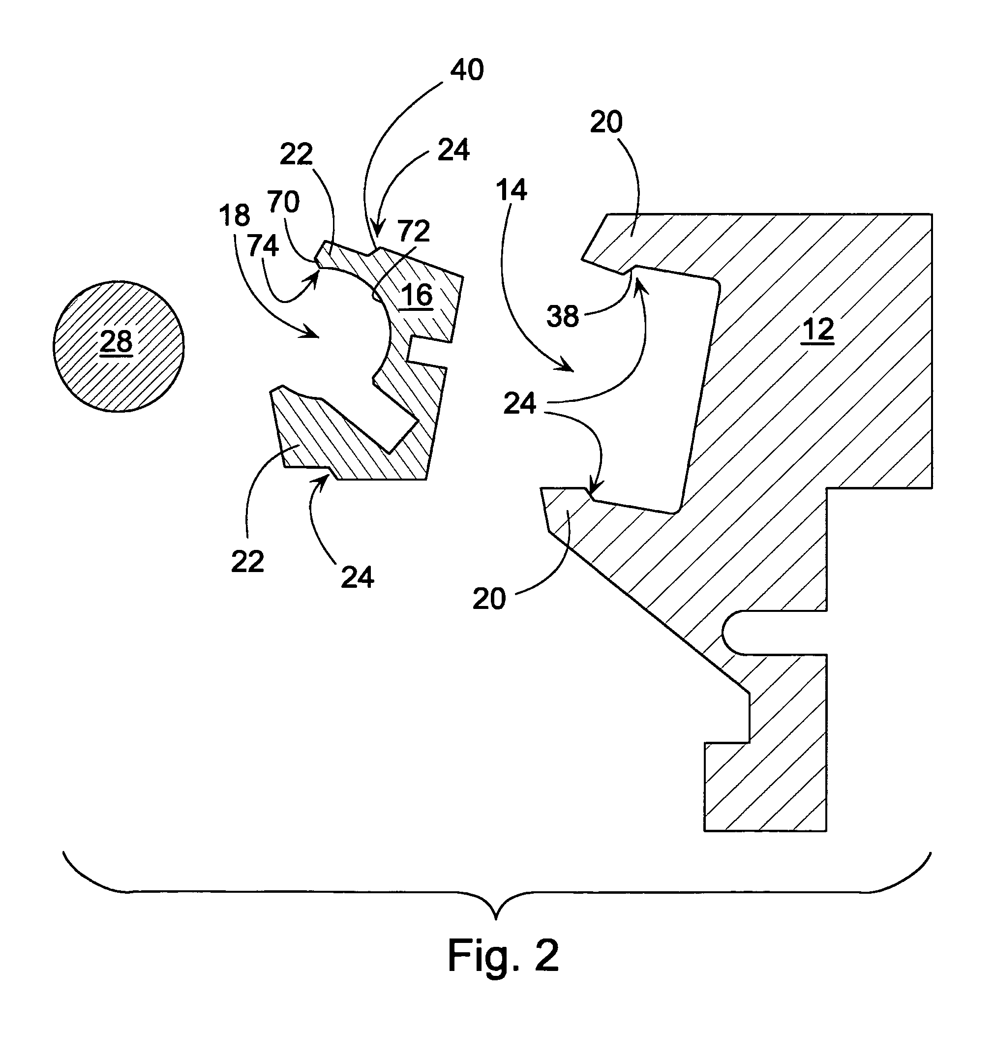
[0012]In a second embodiment, the tangent of the first vertex surface meets the tangent of the second vertex surface between the vertices directly on the side of the rod groove. In that case, the vertex surfaces are shaped in such a way that the rod can be placed in the rod groove when the insert is in the insert groove. In other words, the vertices in the insert will not be damaged, as long as the vertex surfaces are correctly aligned. The rod will also go into the rod groove without damage.
[0017]In a seventh embodiment, the insert is polyethylene, which contains additives improving its wear-resistance, or reducing its friction. The insert, in turn, can be manufactured from polyethylene, polyurethane, or some other material suitable for the purpose, in which there are additives to reduce friction, or to improve wear-resistance or machinability. The insert is preferably of polyethylene. The aim is to optimize the aforementioned properties by adding even several additives to the base material, in such a way that as to achieve an optimal combination of the important properties.
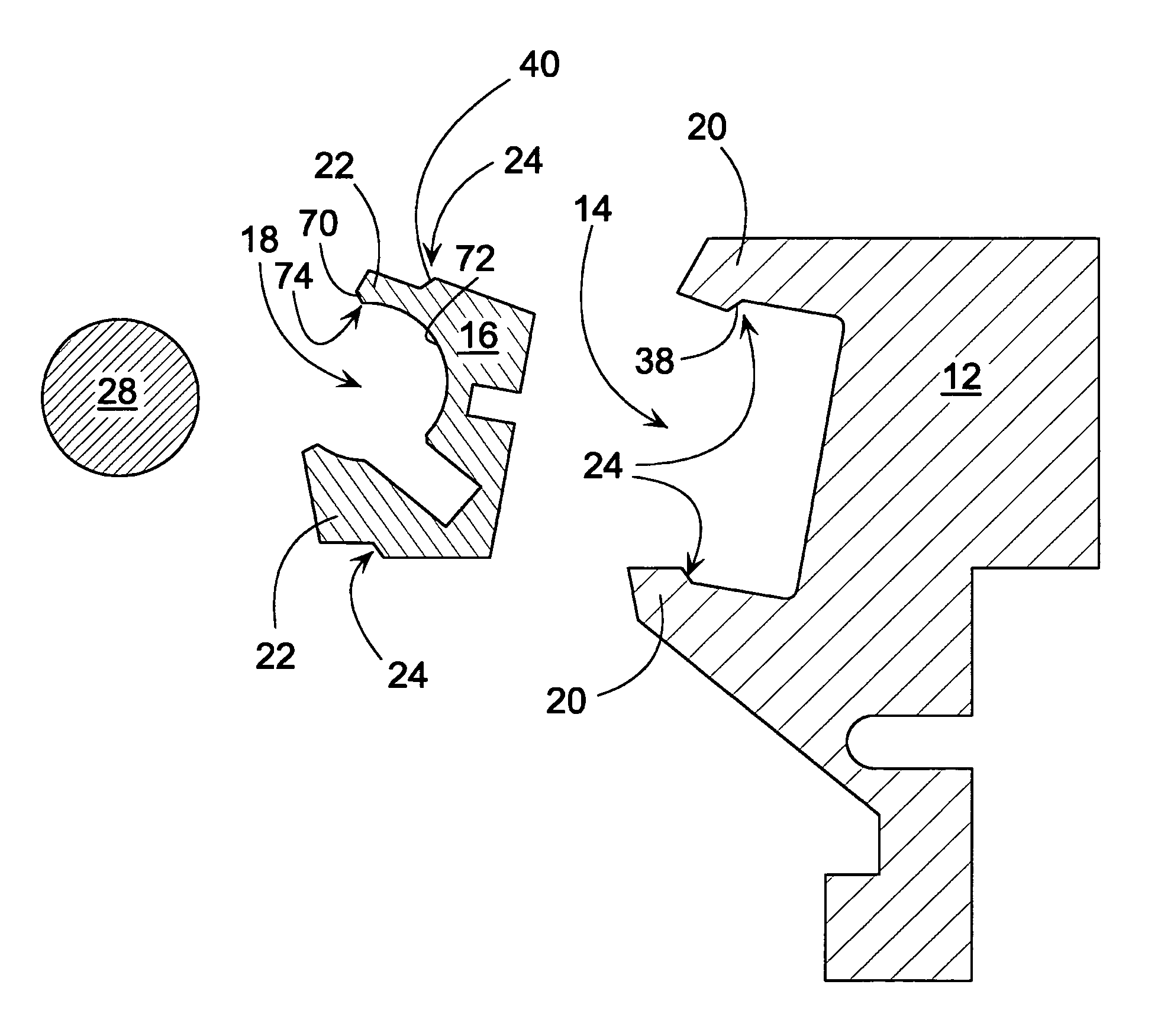
[0019]In a ninth embodiment, the rod cradle includes an insert axial-motion prevention element, which extends on the longitudinal, i.e. axial line of the insert. The axial-motion prevention element prevents the insert from moving in the insert groove in the longitudinal direction of the insert. As the axial-motion prevention element extends radially to the longitudinal line of the insert, movement of the insert is prevented. The axial-motion prevention element can be, for example, a screw, by means of which the insert is attached to the frame profile, or a shaping in the frame profile, which extends radially to the axial line of the insert when the insert is in the insert groove. Of course, a corresponding shaping must be made in the insert, in order that the shaping in the insert groove can lock the insert as desired. In the prior art, the shapes are located in such a way that they are not radially on the longitudinal line of the insert. While the shapes according to the prior art can prevent the insert from jumping out of the insert groove, in the solution according to this embodiment the shapes prevent precisely the axial motion of the insert.
[0020]In a tenth embodiment, the axial-motion prevention element is such that the detaching of the insert from the prevention element can be performed without tools. An axial-motion prevention element of this type can be, for example, the shaping in the insert groove described above. As tools are not required to detach the prevention element, replacing the insert with a new one is extremely easy. In that case, the only tool required for changing the insert can be one, by means of which the insert can be popped out of the groove. The insert can be quickly popped out of the groove, for example, by levering it with a flat-headed screwdriver. If the axial-motion prevention element, for example a screw, needs to be detached by screwing, the replacement of the insert will take considerably longer.
[0022]In a twelfth embodiment, the axial-motion prevention element is attached to the frame profile. When attaching the prevention element to the frame profile, larger screws are used than when attaching the prevention element to the insert, so that the totality is made more durable than when attaching the prevention element to the insert. In addition, attachment to the insert may induce stresses in the insert. Similar stresses in the frame profile will not be as detrimental, as the frame profile has a more massive construction. In addition, the stress acting on the insert acts more easily on the rod, and thus in turn on the coating event.

Problems solved by technology

A rod cradle with an insert is a good solution, as rod cradles must be changed regularly, which leads to spare-parts costs.
When locking the insert using a locking hose, the locking hose must be located in the rod cradle, which is not, however, technically reliable.
A drawback when using the locking-hose technique is the uncertainty of the locking, if pressure is lost for some reason, for example, if the hoses leak, or are wrongly connected.
In addition, the implementation of the hose locking leads to costs, as a separate groove for the hose must be cast or machined.
In addition, the additional grooves in the frame of the rod cradle may cause excessive flexibility in the frame of the rod cradle.
The use of a locking hose is also significant in terms of work safety, as, if the locking hose fractures, the force retaining the insert disappears and the rod or the insert can detach, causing a dangerous situation.
In this embodiment too, the problem is the uncertainty of whether the rod and the insert will remain in the groove, for example, if the loading is momentarily reduced.
In addition, problems can arise when application is starting, when the loading means may not yet be pressing towards the application surface with sufficient force to hold the rod in its groove in the rod cradle.

Method used


Image

  • Rod cradle, instert to be used in a rod cradle, and method for inserting a rod in a rod cradle
  • Rod cradle, instert to be used in a rod cradle, and method for inserting a rod in a rod cradle
  • Rod cradle, instert to be used in a rod cradle, and method for inserting a rod in a rod cradle

Examples


Embodiment Construction

[0035]FIG. 1 shows one rod cradle 10 according to the prior art. The rod cradle 10 includes a frame profile 12 equipped with an insert groove 14. An insert 16, equipped with a rod groove 18, and a rod 28 and locking elements 24 are fitted to the frame profile 12. The locking of the insert 16 to the frame profile 12 takes place using these locking elements. At the sides of the insert groove 14 in the frame profile 12 there are edges 20. At the sides of the rod groove 18 there are lips 22 corresponding to them. The lips 22 include a vertex 74, which is the extreme point of contact with the rod, i.e. the point after which the insert is not in contact with the rod. The lips 22 also include a cover surface 72, 72′ which is in contact with the rod 28, when the rod 28 is in the rod groove 18. In addition, the lips 22 include a vertex surface 70, 70′, which separates from the cover surface 72, 72′ at the vertex 74, 74′. In the solution according to the prior art, the rod is first placed in ...


PUM

PropertyMeasurementUnit
angleaaaaaaaaaa
angleaaaaaaaaaa
angleaaaaaaaaaa

Abstract

A rod cradle for a film, coating, or dam rod includes a frame profile (12) equipped with an insert groove (14), an insert (16) fitted into the insert groove, and the insert having a rod groove (18) and a rod (28) therein. The device has locking elements (24) for locking the insert (16) into the frame profile (12). There are, on the sides of the insert groove, edges (20) through which the insert passes into the insert groove when the rod is not present. On the sides of the rod groove (16) there are opposing lips (22). The lips (22) have vertices (74) through which the rod (28) can pass without damage to the rod or the insert so that the rod can be inserted in to the rod groove (18) and lock the insert (16) in the insert groove (14) of the frame profile.

Description

CROSS REFERENCES TO RELATED APPLICATIONS[0001]This application is a U.S. national stage application of International App. No. PCT / FI2006 / 050523, filed Nov. 28, 2006, the disclosure of which is incorporated by reference herein, and claims priority on Finnish App. Nos. 20055643, filed Dec. 2, 2005, and U20060449, filed Oct. 27, 2006.STATEMENT AS TO RIGHTS TO INVENTIONS MADE UNDER FEDERALLY SPONSORED RESEARCH AND DEVELOPMENT[0002]Not applicable.BACKGROUND OF THE INVENTION[0003]The present invention relates to a rod cradle for a film, coating, or dam rod, which rod cradle includes a frame profile equipped with an insert groove, an insert fitted to this equipped with a rod groove and a rod, and locking elements for locking the insert into the frame profile, and on the sides of the insert groove in the frame profile there are edges and on the sides of the rod groove there are opposing lips corresponding to them, and the lips include a vertex, a cover surface, which cover surface is in con...

Claims


Application Information

Patent Timeline
Patent Type & Authority Patents(United States)
IPC IPC(8): B05C11/04B05D1/40
CPCD21H25/12Y10T29/49826
Inventor KARUSALMI, ARTOKAUTTO, ARI-PEKKAKUPARINEN, SAMILAMBERG, VESAYLONEN, PEKKA
Owner VALMET TECH INC
Why Eureka
Try Eureka