Al technical title is built by PatSnap Al team. It summarizes the technical point description of the patent document.
a technology of mixing syringes and flushing, which is applied in the direction of medical syringes, intravenous devices, syringes for infusion, etc., can solve the problems of large number of mixing syringe parts, dead space, complexity, etc., and achieve the effect of maintaining stability of the valve assembly
Inactive Publication Date: 2006-06-29
INFUSIVE TECH LLC
View PDF38 Cites 19 Cited by
Summary
Abstract
Description
Claims
Application Information
AI Technical Summary
This helps you quickly interpret patents by identifying the three key elements:
Problems solved by technology
Method used
Benefits of technology
[0039] Upon complete evacuation of the liquid from that proximal chamber and by collision of the next valved stopper with the distal internal end surface of the syringe (or another stop), a positive differential pressure across the stopper resulting from force against the syringe stem causes the valve in the next valved stopper to be opened to a second state. Thus, continuous action upon the stem of the syringe permits sequential and selective dispensing of liquid contents from each such proximal chamber following dispensing of fluid from each more distal chamber. In the embodiment where mixing is dependent upon a positive differential pressure, there is no need to switch an associated valve to a second state, as the valve is already open to dispense fluids from the syringe.
[0040] It is important to note that conditions which inhibit reflux, guard against dispensing gas from the most proximal chamber, maintain stability of the valve assembly as it is displaced within a syringe barrel and assure low resistance to dispensing flow in the mixing syringe assembly / multi-chamber syringe combination are the same as for the multi-chamber syringe, disclosed in Thorne, Jr.
Problems solved by technology
Beyond the requirement for special barrel design, there may be performance issues associated with such syringes, such as dead space and numbers of mixing syringe parts and complexity.
Method used
Image
Click on the blue label to locate the original text in one second.
Reading with bidirectional positioning of images and text.
Examples
Embodiment Construction
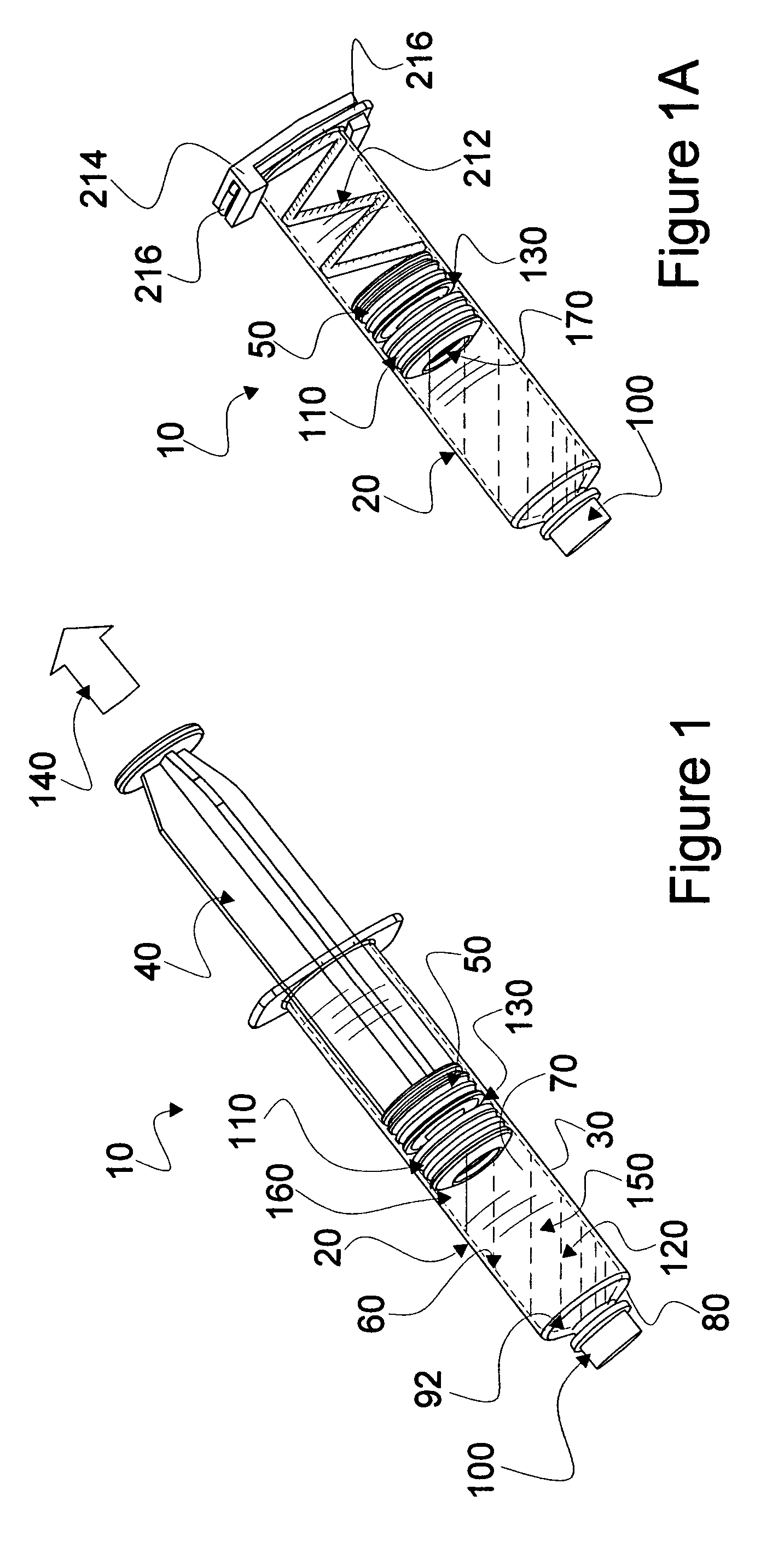
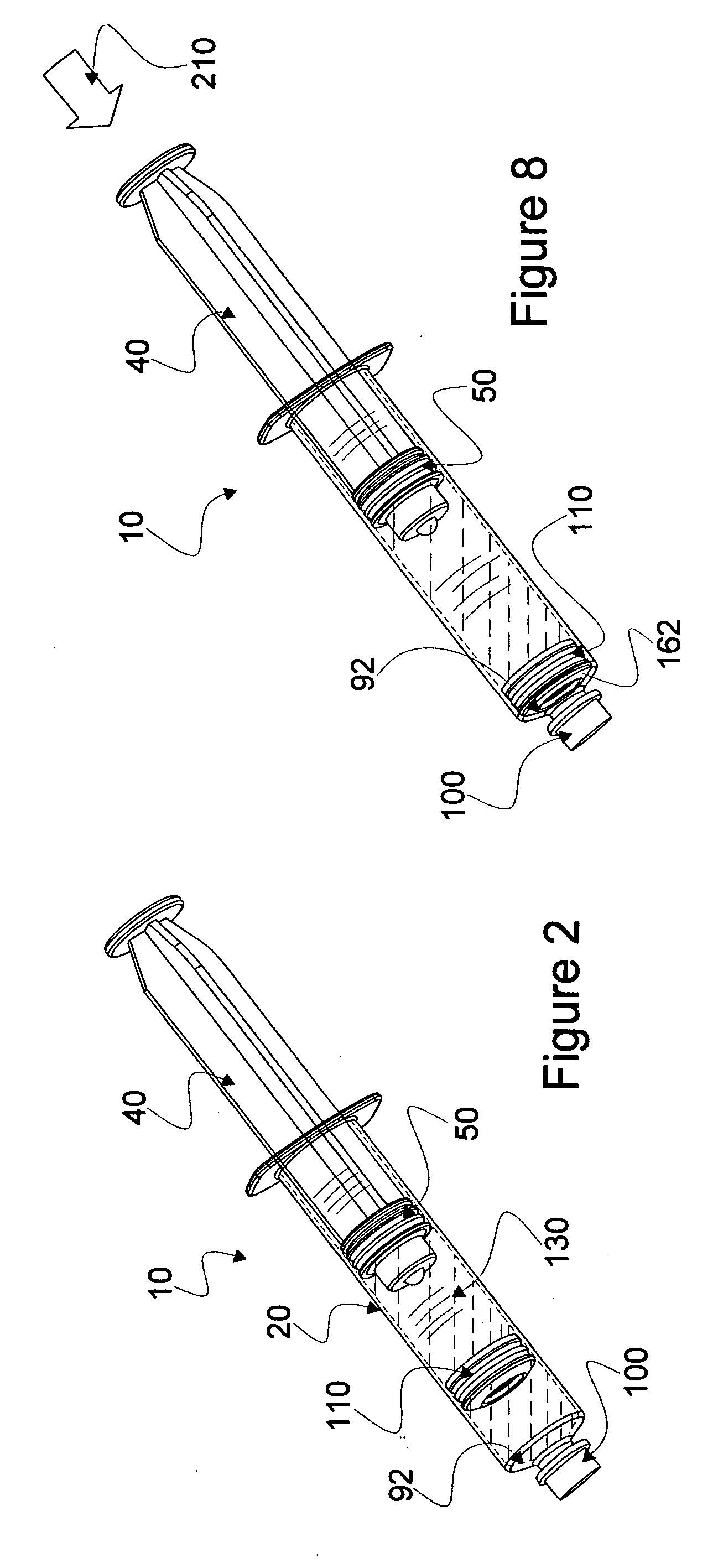
[0084] In this description, primes of numbers are used to represent parts which are similar, but not identical to other parts having the same numbers. Reference is now made to embodiments illustrated in FIGS. 1-25 wherein like numerals are used to designate like parts throughout. Note that FIGS. 1-21 generally disclose elements associated with a first embodiment of the instant invention whileFIGS. 22-25 disclose elements associated with a second embodiment of the instant invention.
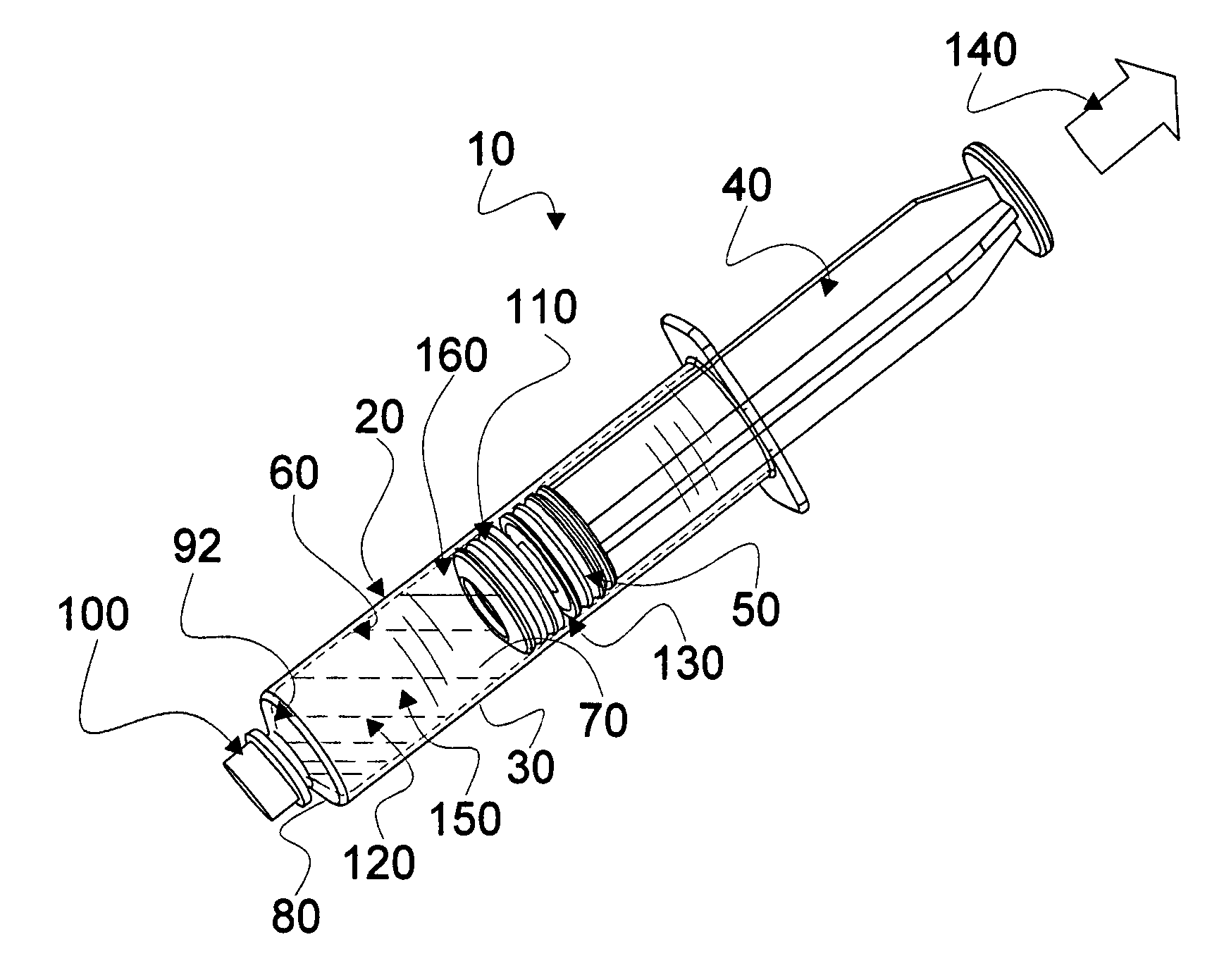
[0085] Reference is now made to FIG. 1 wherein a two chamber mixing syringe assembly 10 made according to the instant invention is seen. Mixing syringe assembly 10 is assembled using a conventional syringe 20 which comprises a traditional elongated, cylindrical barrel 30, a stem 40 and a plunger 50 associated with stem 40.
[0086] Plunger 50, as is the case for most syringe plungers, is disposed within a hollow cylinder 60 of barrel 30 and is sufficiently close fitting to be fluid tight and wipe liquid fro...
PUM
Abstract
A displaceable valved stopper is disclosed which partitions a conventional syringe into proximal and distal chambers to provide a multi-chamber, mixing syringe assembly. Also the valved stopper and a valve assembly are disclosed for use in a single conventional syringe to provide dual chamber mixing plus a disparate and sequentially dispensed flush. Incorporated in the valve assembly is another valved stopper and a separator which filters out gas from liquid being dispensed through the valve assembly. Each valved stopper is made as a single molded part which may be made from basic syringe plunger material. Also, each valved stopper may have a bi-state valve (e.g. a domed, slit valve). The separator is a single molded part which may be molded from basic syringe material. Each valve is actuated to a different state by differential pressure of a force greater than the associated valved stopper displacement force. A syringe plunger communicates through fluid in a more proximal chamber to force displacement of the valved stopper and valve assembly for both mixing and dispensing.
Description
CONTINUATION-IN-PART [0001] This Patent application is a Continuation-in-Part of U.S. patent application Ser. No. 11 / 284,504 titled MULTI-CHAMBER, SEQUENTIAL DOSE DISPENSING SYRINGE, filed by Gale H. Thorne, Jr. et al. (Thorne, Jr.) on Nov. 22, 2005; which is a Continuation-in-Part of U.S. patent application Ser. No. 10 / 838,101, titled MULTI-CHAMBER, SEQUENTIAL DOSE DISPENSING SYRINGE, filed by Howlett, et al. (Howlett) on May 3, 2004, for which a U.S. Pat. No. 6,997,910 has been issued, and, for which an international PCT patent application number of PCT / US05 / 14299 was filed Apr. 26, 2005.FIELD OF INVENTION [0002] This invention relates to mixing syringes and multi-chamber syringes and, in particular, to mixing syringes which utilize conventional syringe barrels and, in the case of multi-chamber flush syringes, dispense fluid from each chamber sequentially. DESCRIPTION OF RELATED ART [0003] This invention is a Continuation-in-Part of Thorne, Jr. which discloses multi-chamber syring...
Claims
Application Information
Patent Timeline
Application Date:The date an application was filed.
Publication Date:The date a patent or application was officially published.
First Publication Date:The earliest publication date of a patent with the same application number.
Issue Date:Publication date of the patent grant document.
PCT Entry Date:The Entry date of PCT National Phase.
Estimated Expiry Date:The statutory expiry date of a patent right according to the Patent Law, and it is the longest term of protection that the patent right can achieve without the termination of the patent right due to other reasons(Term extension factor has been taken into account ).
Invalid Date:Actual expiry date is based on effective date or publication date of legal transaction data of invalid patent.
Patent Type & Authority Applications(United States)