

Interlabial pad
a technology of interlabial pads and pads, which is applied in the field of interlabial pads, can solve the problems of reducing the rigidity of the interlabial pads, and falling away from the labia of the wearer, so as to facilitate bending and reduce the rigidity. , the effect of low flexural rigidity
- Summary
- Abstract
- Description
- Claims
- Application Information
AI Technical Summary
Benefits of technology
Problems solved by technology
Method used
Image

Examples
first embodiment
Overall Construction of the Interlabial Pad
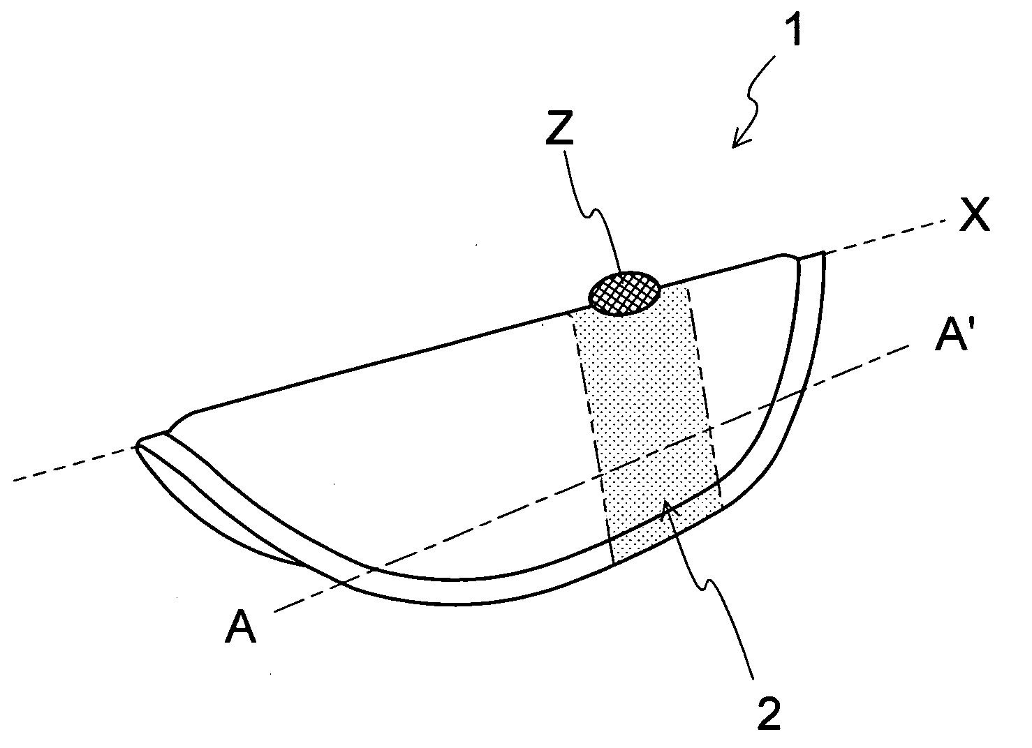
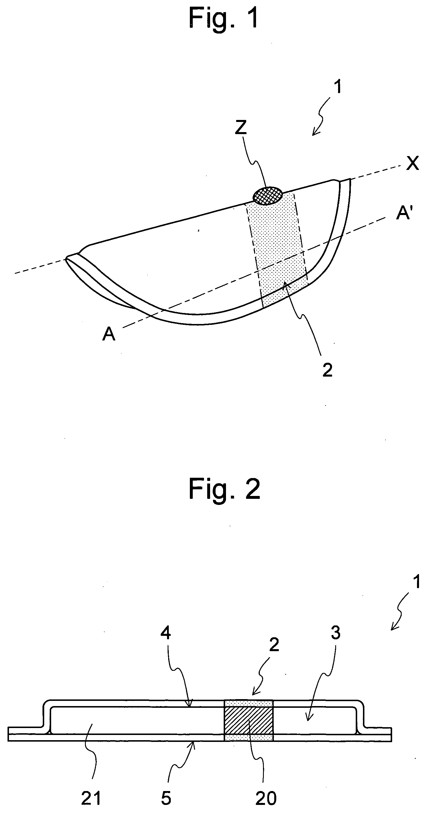
[0060]FIG. 1 shows a perspective view of interlabial pad 1 according to this embodiment. The interlabial pad 1 is a substantially oval plate having a surface which is longer in a direction parallel to a central folding axis (hereinafter called “central folding axis direction”) X than in a lateral direction roughly perpendicular to the central folding axis. The interlabial pad 1 is folded with the central folding axis as the folding line and is worn such that at least a part is held between the labia minora so that at least a part in the vicinity of the central folding axis contacts the vestibular floor within the labia of a wearer. The interlabial pad 1 has a pair of strip-shaped areas which extends towards the side-edges, the side-edges are parallel to the central folding axis, and in an area of each of the strip-shaped areas, the area includes at least one of the side-edges of these strip-shaped areas, includes a low flexural rigidity p...
second embodiment
Slit Processing of Absorbent Member 3a
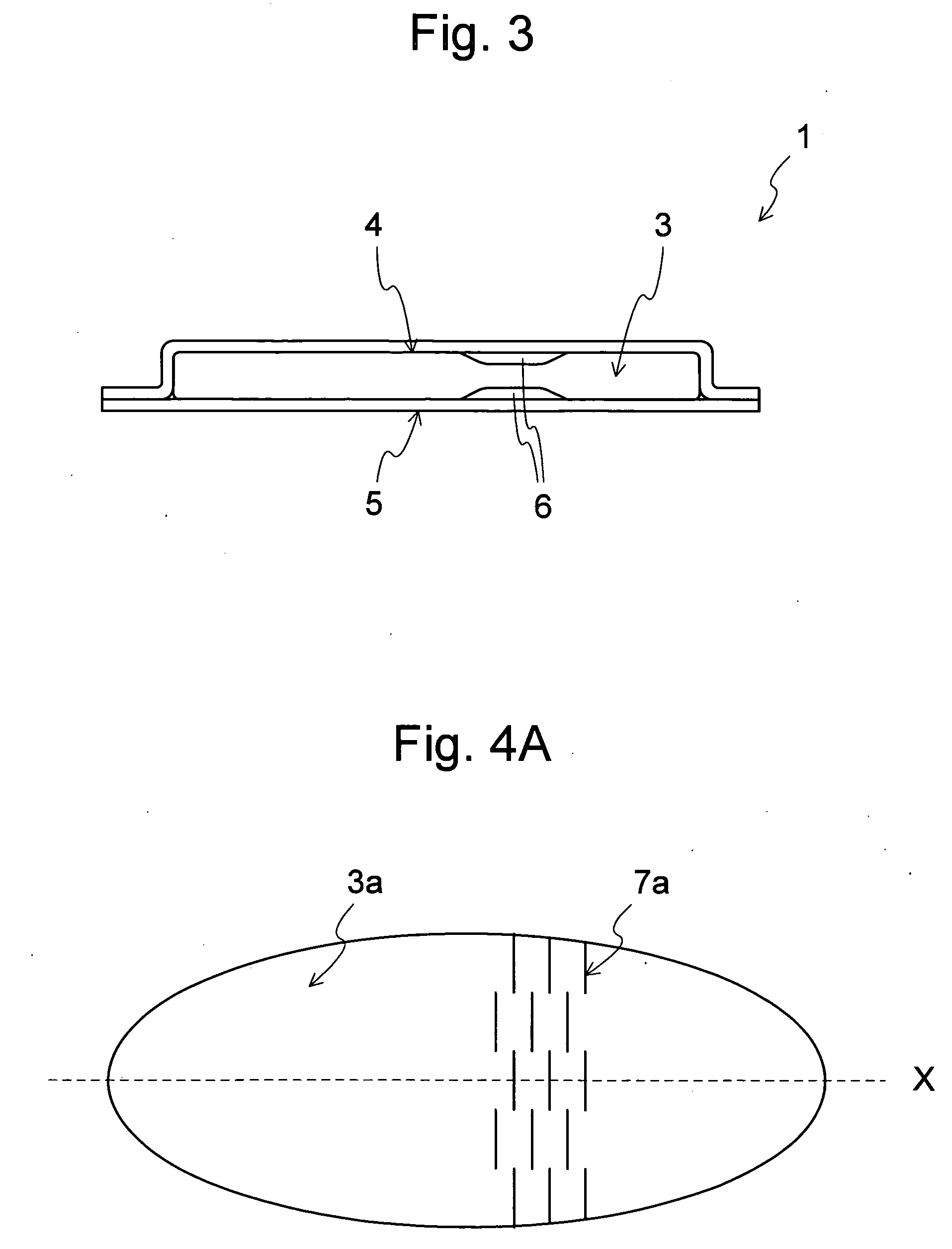
[0085]FIG. 4A is a top view of an absorbent member 3a of a flat interlabial pad. The absorbent member 3a of the interlabial pad in FIG. 4A is one in which slits facing the direction perpendicular to the central folding axis are provided in the area (the first part) to become the low flexural rigidity part of the absorbent member 3a, in order to facilitate bending of interlabial pad in the central folding axis direction X, and constituents excluding this are the same as that of the first embodiment. In the second embodiment, the shape of slit 7a is not particularly limited and can be linear, curved, wavy, and the like. The length of one slit 7a is preferably within the range of 1 mm or more and 20 mm or less, and the distance between slits 7a is preferably within the range of 1 mm or more and 20 mm or less. Furthermore, the slit 7a according to the present invention may or may not penetrate the absorbent member 3a in the thickness direction.
[0...
third embodiment
Interlacing of Fibers in the Absorbent Member 3b
[0087]FIG. 4B is a cross sectional view of an interlabial pad 1b according to a third embodiment cut along the central holding axis. The interlabial pad 1b of the third embodiment is one which uses material in which the fibers are not easily interlaced as material comprising a part (a first part) 20b of an absorbent member 3b, the part is positioned in the corresponding of the low flexural rigidity part 2b, and constituents excluding this are the same as that of the first embodiment. As materials, in which the fibers are not easily interlaced, fibers which contain a high percentage of thick denier fibers, for example, can be given. If the percentage of the thick denier fibers contained is high, the fibers become less prone to interlacing and the distance between the fibers becomes wider than that in the surrounding areas (the second part) 21b, and therefore, the flexural rigidity in the low flexural rigidity part 2b becomes low and t...
PUM
 Abstract
Description
Claims
Application Information