
System and method for fault detection and recovery

a technology applied in the field of fault detection and recovery, can solve problems such as hardware faults, software faults, complex software,

Inactive Publication Date: 2006-06-29
INTEL CORP
View PDF10 Cites 45 Cited by
  • Summary
  • Abstract
  • Description
  • Claims
  • Application Information

AI Technical Summary

Benefits of technology

The system provides a formal and comprehensive approach to fault detection and recovery, enabling automatic fault handling and minimizing system downtime by allowing for customizable recovery strategies and independent operation from software processes, thus improving system reliability and reusability.

Problems solved by technology

Many of these systems are sophisticated and have complex software for driving the operation of the microprocessor and other hardware components.
These faults can be hardware faults or software faults resulting from hardware or software malfunctions.
In most microprocessor-based systems, fault detection and recovery is not implemented.
In those rare cases where fault detection and recovery is implemented, the implementation is relatively primitive and informal.
Specifically, it is typically left to the discretion of the hardware and software developers to design fault detection and recovery into their software processes which creates many problems.
For example, any fault detection and recovery that does exist is tightly coupled and intertwined with the software process so re-use is difficult or impossible.
This is especially true since software and hardware faults are typically handled by separate modules and not by one integrated module.
Additional problems arise since many software processes are designed to exit when a fault occurs requiring the system to be manually restarted or rebooted to resume operation.

Method used


Image

  • System and method for fault detection and recovery
  • System and method for fault detection and recovery
  • System and method for fault detection and recovery

Examples


Embodiment Construction

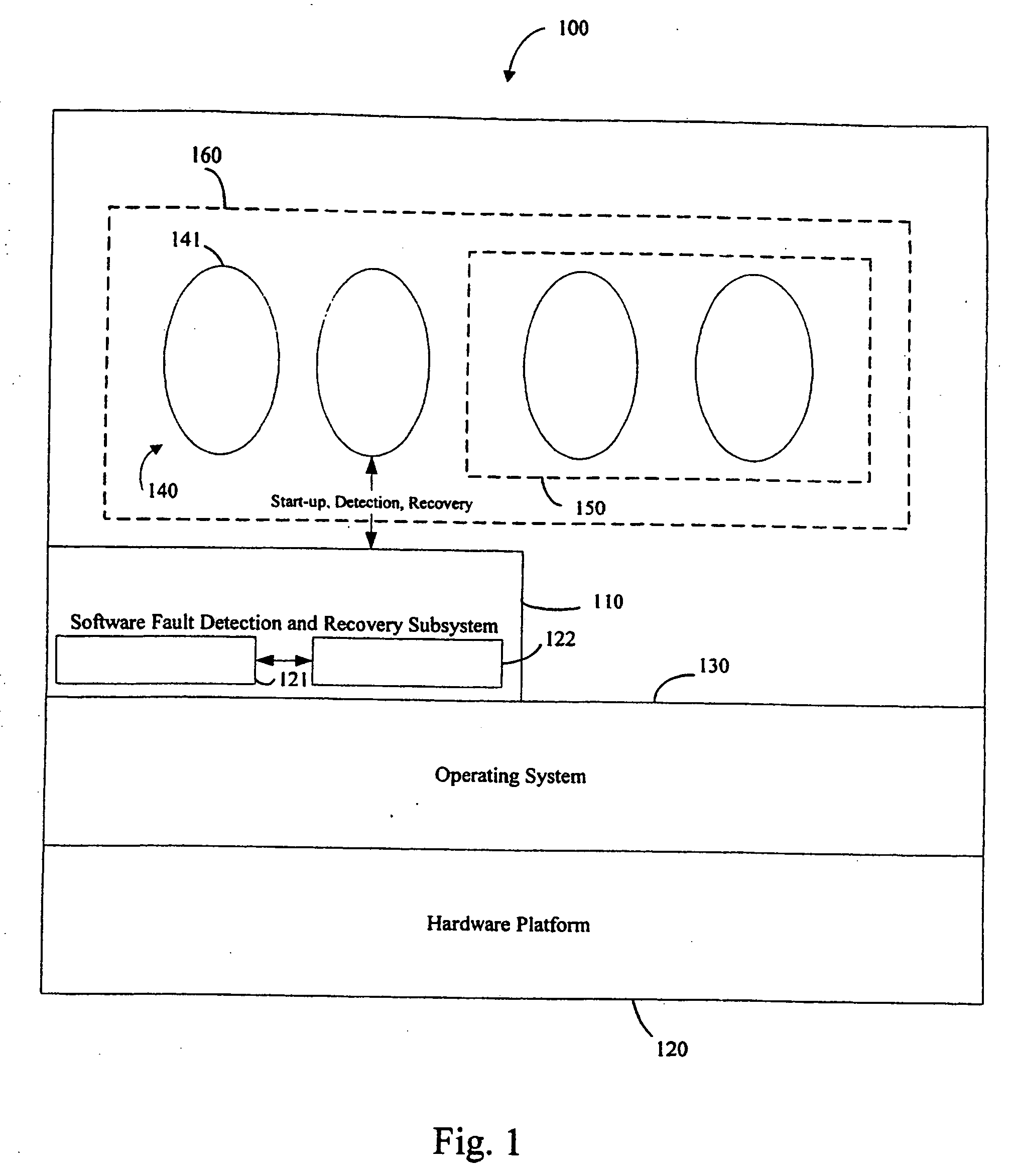
[0013] Turning now to the figures, wherein like reference numerals refer to like elements, FIG. 1 illustrates a block diagram of an exemplary microprocessor-based system 100 that includes the fault detection and recovery subsystem 110 of the present invention. The microprocessor-based system 100 includes a hardware platform 120, an operating system 130, the fault detection and recovery subsystem 110 of the present invention, and software processes 140. The hardware platform includes a microprocessor. The operating system 130 can be any type of operating system and is embodied in software that resides on the hardware platform 120. The fault detection and recovery subsystem 110 is embodied in software that also resides on the hardware platform 120. The fault detection and recovery subsystem 110 can be divided into modules such as a first module 121 and a second module 122. The software processes 140 can be any type of software processes written in any programming language. The term “p...


PUM


Abstract

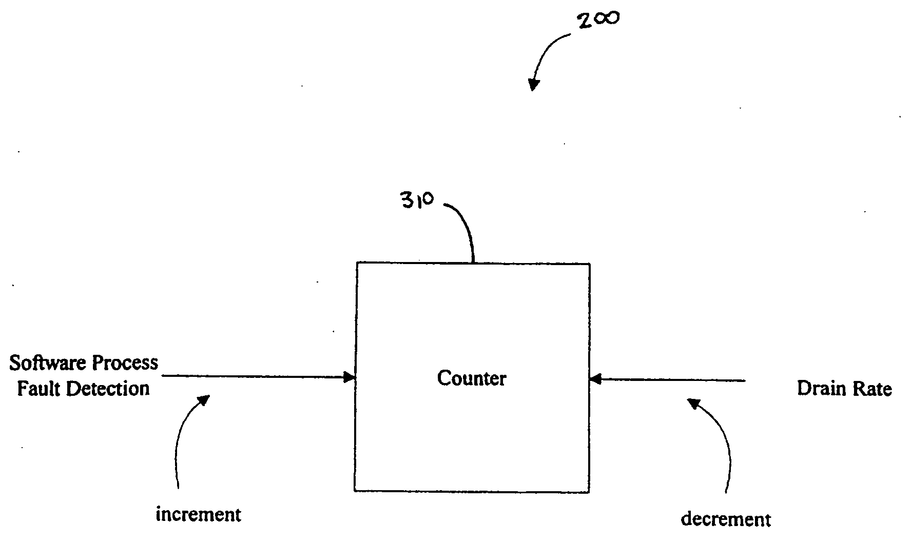
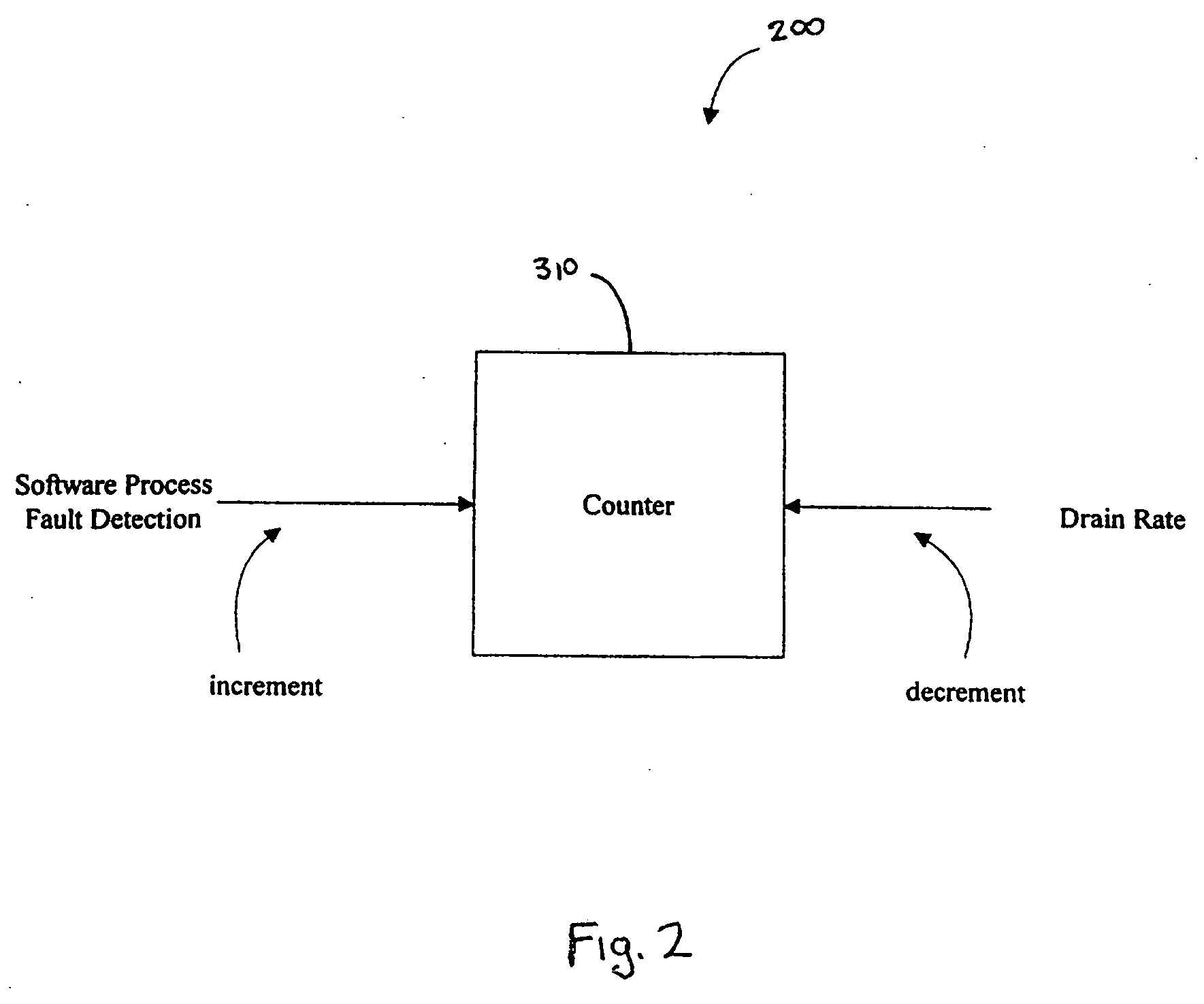
An apparatus and method for automatically detecting and recovering from a fault in a microprocessor-based system. The apparatus and method utilizes a leaky bucket routine and an event handler procedure. The method may further use Object Oriented techniques that abstracts differences between hardware and software faults to allow for the development of a common framework.

Description

RELATED APPLICATION [0001] This application claims the benefit of U.S. Provisional Patent Application Ser. No. 60 / 333,871 filed on Nov. 28, 2001 and which is incorporated herein by reference in its entirety.BACKGROUND OF THE INVENTION [0002] The present invention relates generally to fault detection and recovery and, more particularly, relates to a system and method for automatically detecting and recovering from software and / or hardware faults in microprocessor-based systems. [0003] Microprocessor-based systems are used in an increasing number of applications, in part, because present day microprocessors are inexpensive and extremely powerful. Many of these systems are sophisticated and have complex software for driving the operation of the microprocessor and other hardware components. Since many of these systems, such as a router in a computer network, must operate continuously and unattended, the systems must be designed to operate in the presence of faults. These faults can be h...

Claims


Application Information

Patent Timeline
Patent Type & Authority Applications(United States)
IPC IPC(8): G06F11/00
CPCG06F11/0715G06F11/076G06F11/0793
Inventor LEDUC, DOUGLAS E.LASH, JOHN K.KOLLURU, NAGENDRA V.
Owner INTEL CORP
Learn More