Traveling device used between adjacent train bodies of motor train unit and capable of reducing floor height

The technology of a running device and an EMU is applied in the direction of the lateral relative moving device between the underframe and the bogie, the railway car body, and the parts of the railway car body. and other problems, to achieve the effect of improving the ability to pass the curve and turning maneuverability, improving the patency, and making it easier to pedal and get off.

Active Publication Date: 2016-04-06
CRRC CHANGCHUN RAILWAY VEHICLES CO LTD
View PDF5 Cites 18 Cited by
  • Summary
  • Abstract
  • Description
  • Claims
  • Application Information

AI Technical Summary

Problems solved by technology

[0004] In order to solve the problem that the existing EMU trains composed of four-axle vehicles cannot meet the special requirements of lowering the center of gravity and floor height of the vehicles and making it convenient for passengers to get on and off, and can not meet the standard of barrier-free passage between different vehicles without steps. To solve the technical problem, the present invention provides a running device that can reduce the floor height between adjacent car bodies of EMUs

Method used


Image

  • Traveling device used between adjacent train bodies of motor train unit and capable of reducing floor height
  • Traveling device used between adjacent train bodies of motor train unit and capable of reducing floor height
  • Traveling device used between adjacent train bodies of motor train unit and capable of reducing floor height

Examples


Embodiment Construction

[0020] The present invention will be described in further detail below in conjunction with the accompanying drawings.

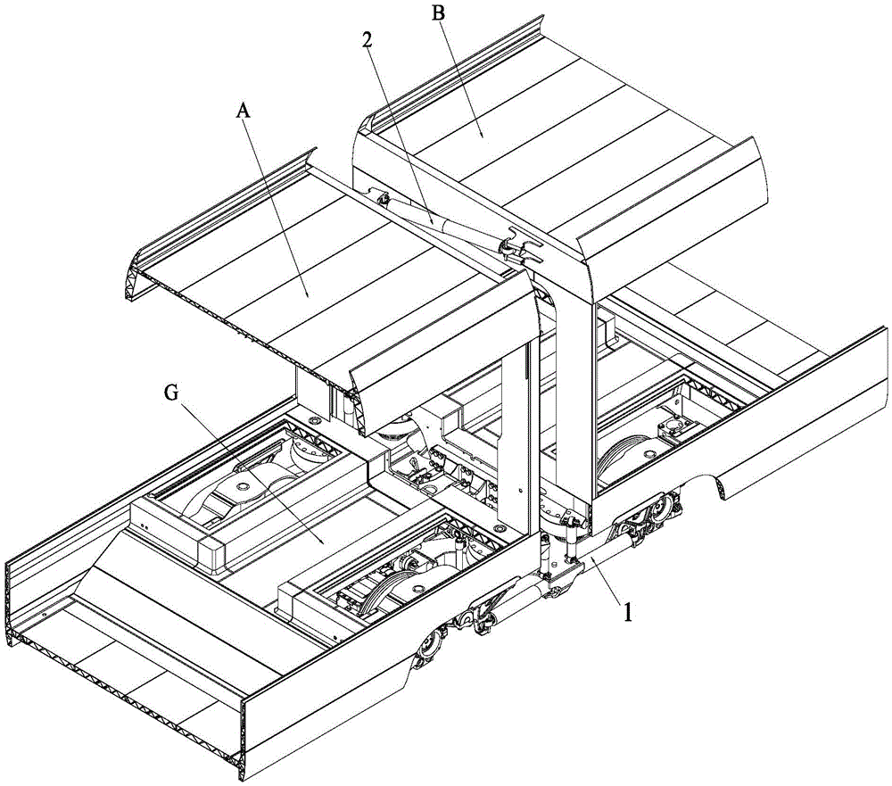
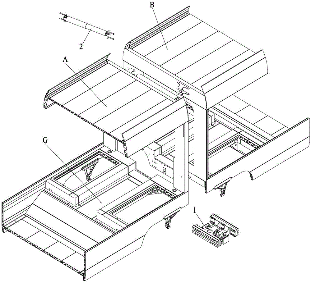
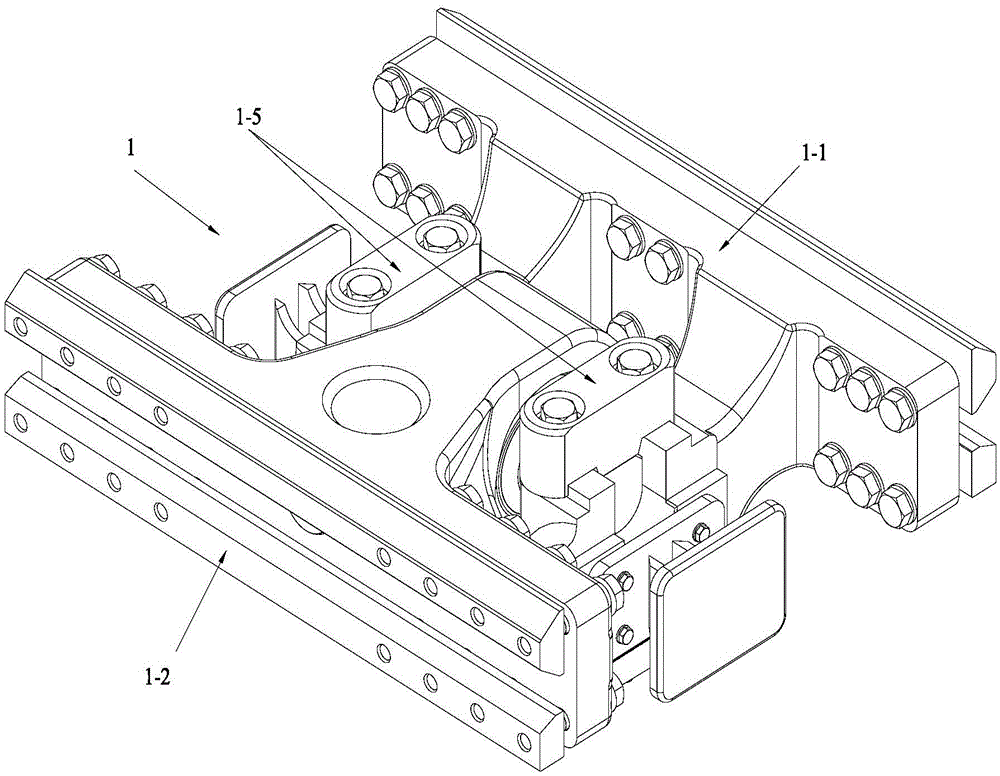
[0021] Such as Figure 1 to Figure 9 As shown, a traveling device of the present invention that can reduce the floor height between adjacent car bodies of an EMU includes a common connection device 1 , an oil pressure shock absorber 2 and a common bogie 3 . The hydraulic shock absorber 2 is arranged laterally between two adjacent carriages, and its two ends are respectively fixed on the sides of the roofs of the adjacent two carriages through metal rubber joints, and are used to suppress the gap between the tops of carriages A and B. The relative rolling vibration of the vehicle improves the running stability and ride comfort of the vehicle. The two ends of the common connecting device 1 are respectively fixed on the bottom frame end beams of two adjacent cars, and the two ends of the common bogie 3 are respectively fixed on the bottom frames of two adjacent...


PUM


Abstract

The invention belongs to the field of connection systems for every two adjacent carriages of a railway vehicle and relates to a traveling device used between adjacent train bodies of a motor train unit and capable of reducing the floor height. The traveling device is a low-gravity-center compact common bogie of a brand new form. An oil damper of the traveling device is used for restraining relative rolling pendulum vibration between the top of a carriage A and the top of a carriage B. The two ends of a common connecting device are fixed to underframe end beams of the two adjacent carriages respectively. Four air spring installation positions arranged on two sides are uniquely arranged on a common framework so as to contain sleeper beam middle through grooves. Under the condition that the existing fixed distance of each carriage of the motor train unit is kept unchanged, the traveling device can reduce the total number of bogies of the motor train unit and reduce the manufacturing cost of the motor train unit; moreover, while the un-obstruction performance of the interior floor of the motor train unit is improved, the overall gravity center and the floor height of the motor train unit are lowered, and passengers can conveniently get on or off the motor train unit. In addition, the traveling device remarkably improves the bend curve passage capacity and the turning maneuvering performance of the motor train unit.

Description

technical field [0001] The invention belongs to the field of a connection system between two adjacent carriages of a rail vehicle, and in particular relates to a traveling device used for reducing the floor height between adjacent carriages of an EMU. Background technique [0002] Rail trains whose floor surface is 600mm to 800mm in height from the track plane have many advantages. This type of train model with ideal structure has excellent adaptability to the track infrastructure. The construction cost of the new high platform, and its low center of gravity and relatively short vehicle spacing enable the train to obtain the high-efficiency curve passing ability of flexible turning within a smaller radius. In addition, the ideal structure of the train The model also has a low-height through-floor structure that runs through all the cars, allowing passengers to pass between different cars without barriers, without the need to cross the steps between the cars, especially to fa...

Claims


Application Information

Patent Timeline
Patent Type & Authority Applications(China)
IPC IPC(8): B61D17/20B61F3/12B61G5/02B61F5/04B61F5/24B61F5/30
CPCB61D17/20B61F3/12B61F5/04B61F5/24B61F5/30B61G5/02
Inventor 陆海英李稳程冰
Owner CRRC CHANGCHUN RAILWAY VEHICLES CO LTD
Why Eureka
Try Eureka