Eureka AIR delivers breakthrough ideas for toughest innovation challenges, trusted by R&D personnel around the world.

Cooling device and electronic device

Inactive Publication Date: 2006-07-06
FUJITSU LTD
View PDF10 Cites 15 Cited by
  • Summary
  • Abstract
  • Description
  • Claims
  • Application Information

AI Technical Summary

Benefits of technology

[0013] According to an aspect of the present invention, a cooling device includes a heat pipe; an attaching member that attaches an electronic component to one surface on one side of the heat pipe so that the heat pipe can absorb heat of the electronic component; a first heat-radiating fin attached to another surface on another side of the heat pipe; a first fan unit that produces an airflow and directs the airflow toward the first heat-radiating fin; and a first duct that guides the airflow produced by the first fan unit to the first heat-radiating fin.
[0013] According to an aspect of the present invention, a cooling device includes a heat pipe; an attaching member that attaches an electronic component to one surface on one side of the heat pipe so that the heat pipe can absorb heat of the electronic component; a first heat-radiating fin attached to another surface on another side of the heat pipe; a first fan unit that produces an airflow and directs the airflow toward the first heat-radiating fin; and a first duct that guides the airflow produced by the first fan unit to the first heat-radiating fin.
[0013] According to an aspect of the present invention, a cooling device includes a heat pipe; an attaching member that attaches an electronic component to one surface on one side of the heat pipe so that the heat pipe can absorb heat of the electronic component; a first heat-radiating fin attached to another surface on another side of the heat pipe; a first fan unit that produces an airflow and directs the airflow toward the first heat-radiating fin; and a first duct that guides the airflow produced by the first fan unit to the first heat-radiating fin.
[0013] According to an aspect of the present invention, a cooling device includes a heat pipe; an attaching member that attaches an electronic component to one surface on one side of the heat pipe so that the heat pipe can absorb heat of the electronic component; a first heat-radiating fin attached to another surface on another side of the heat pipe; a first fan unit that produces an airflow and directs the airflow toward the first heat-radiating fin; and a first duct that guides the airflow produced by the first fan unit to the first heat-radiating fin.
[0013] According to an aspect of the present invention, a cooling device includes a heat pipe; an attaching member that attaches an electronic component to one surface on one side of the heat pipe so that the heat pipe can absorb heat of the electronic component; a first heat-radiating fin attached to another surface on another side of the heat pipe; a first fan unit that produces an airflow and directs the airflow toward the first heat-radiating fin; and a first duct that guides the airflow produced by the first fan unit to the first heat-radiating fin.
[0011] The present invention has been made in view of the above problems. An object of the present invention is to provide a compact cooling device for an electronic component with improved cooling ability.
[0013] According to an aspect of the present invention, a cooling device includes a heat pipe; an attaching member that attaches an electronic component to one surface on one side of the heat pipe so that the heat pipe can absorb heat of the electronic component; a first heat-radiating fin attached to another surface on another side of the heat pipe; a first fan unit that produces an airflow and directs the airflow toward the first heat-radiating fin; and a first duct that guides the airflow produced by the first fan unit to the first heat-radiating fin.
[0013] According to an aspect of the present invention, a cooling device includes a heat pipe; an attaching member that attaches an electronic component to one surface on one side of the heat pipe so that the heat pipe can absorb heat of the electronic component; a first heat-radiating fin attached to another surface on another side of the heat pipe; a first fan unit that produces an airflow and directs the airflow toward the first heat-radiating fin; and a first duct that guides the airflow produced by the first fan unit to the first heat-radiating fin.

Problems solved by technology

The operation of the electronic component generally becomes unstable if the temperature of an electronic component exceeds a certain value.
Accordingly, a problem arises in that an airflow produced by the fan unit 9 does not flow evenly throughout the entire heat radiating fin 7, and therefore, the cooling ability is low.

Method used


Image

  • Cooling device and electronic device
  • Cooling device and electronic device
  • Cooling device and electronic device

Examples


first embodiment

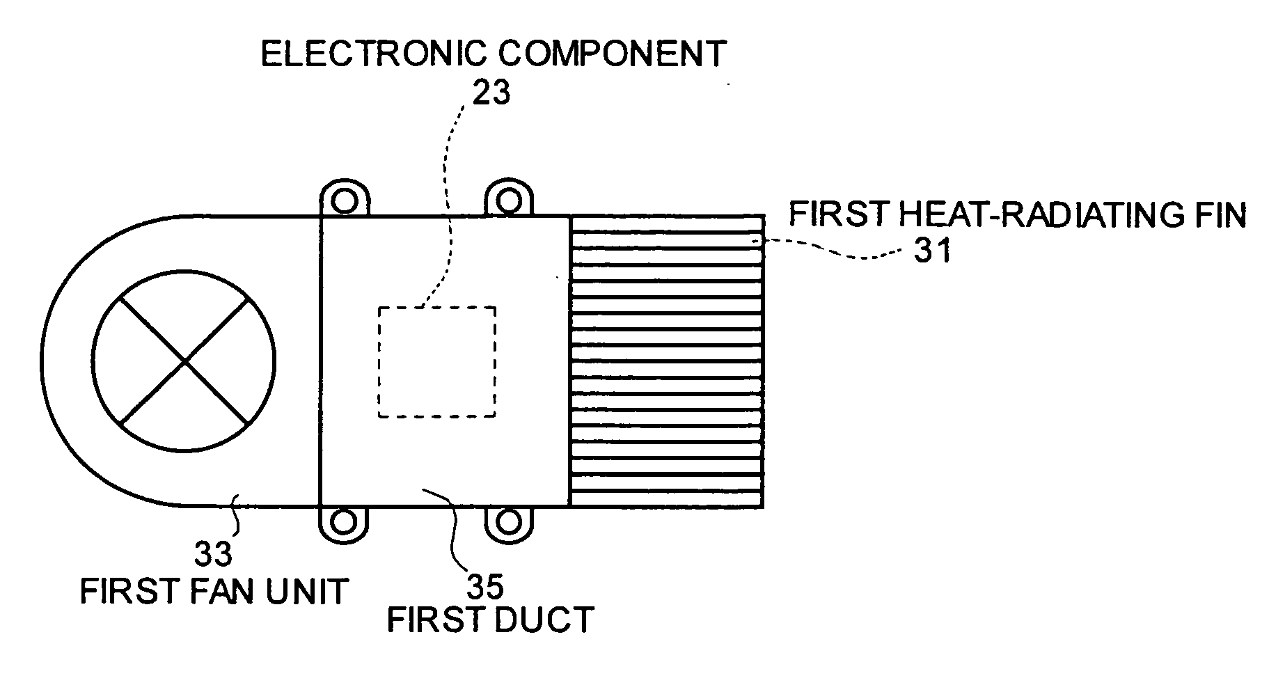
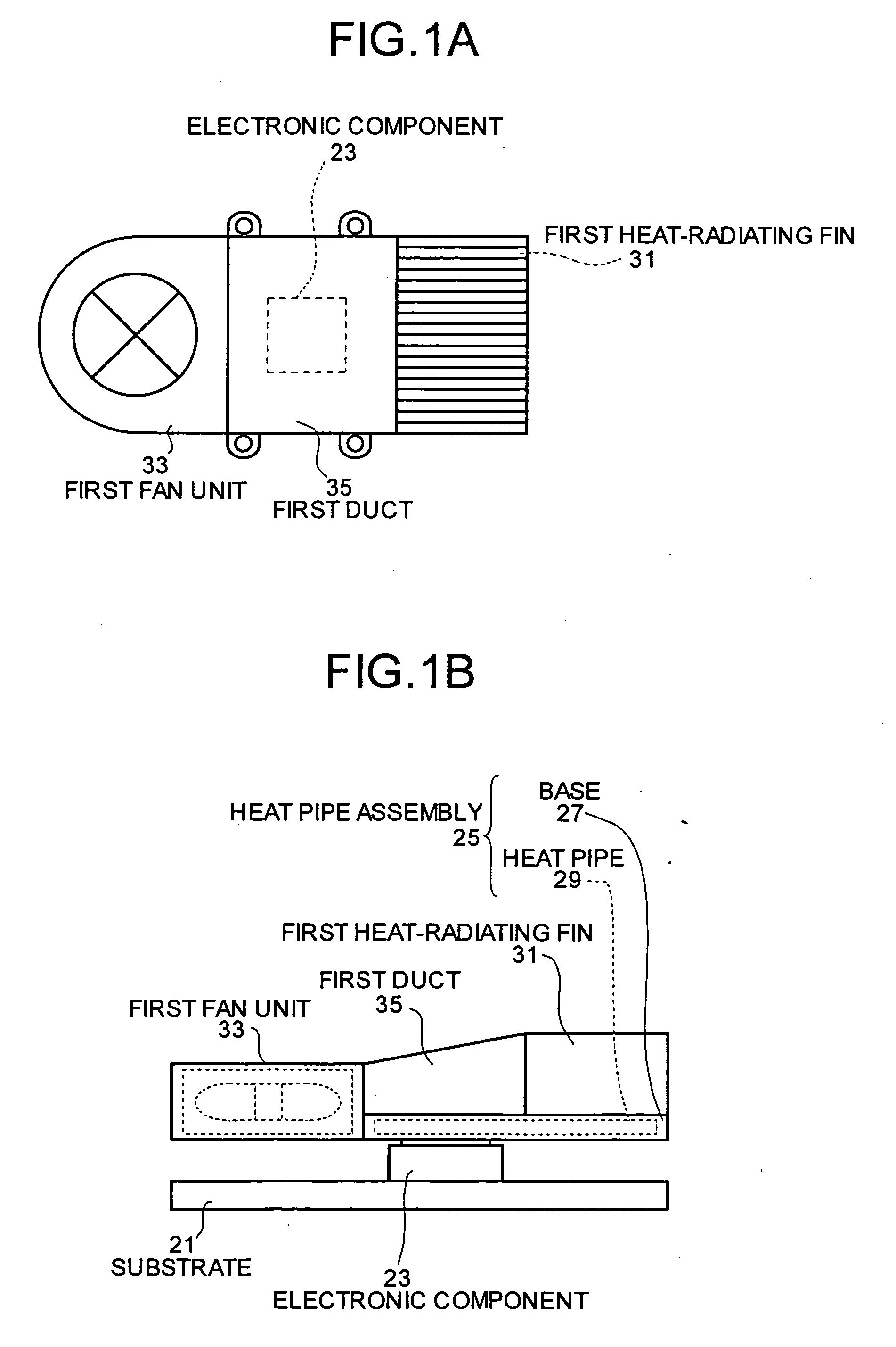
[0024] the present invention is described below with reference to FIGS. 1A and 1B. FIG. 1A is a top view, and FIG. 1B is a side view of FIG. 1A.

[0025] As shown in the figures, an electronic component 23 that generates heat is provided on a substrate 21. A bottom surface (one surface) on one side of a planer heat pipe assembly 25 is attached on the electronic component 23. The heat pipe assembly 25 includes a base 27 made of a material of high heat conductivity and a planer heat pipe 29 provided inside the base 27. A first heat-radiating fin 31 is provided on a top surface (other surface) of the heat pipe assembly 25. A first fan unit 33 is provided on one side of the heat pipe assembly 25. Further, a first duct 35 that guides an airflow produced by the first fan unit 33 to the first heat-radiating fin 31 is provided on the top surface of the heat pipe assembly 25.

[0026] An operation of cooling is performed in the following manner.

[0027] The first fan unit 33 produces airflow. The ...

fourth embodiment

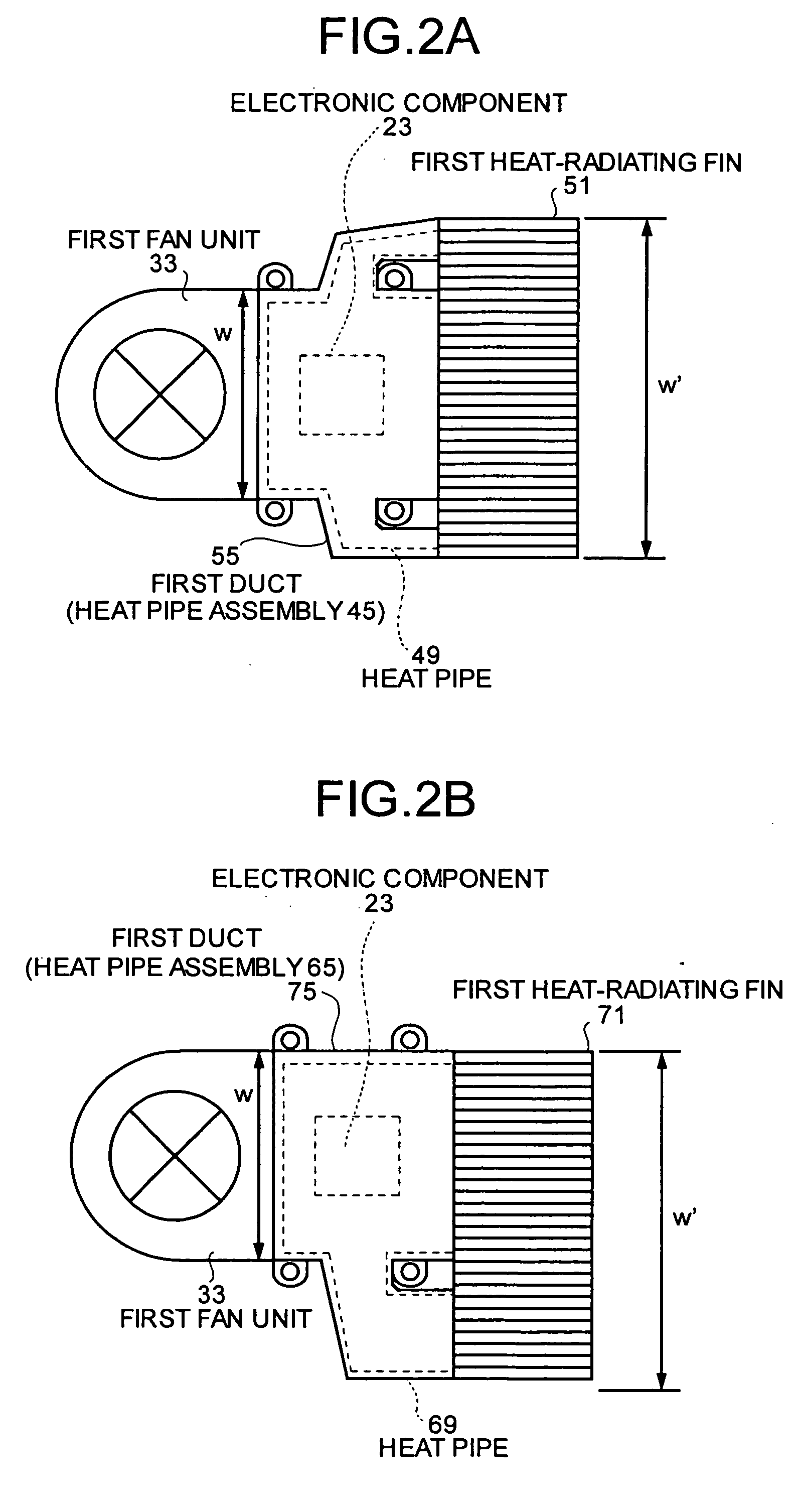
[0059] According to the above configuration, similarly to the fourth embodiment, heat is discharged from both the first heat-radiating fin 31 and the second heat-radiating fin 331, so that the total amount of discharged heat increases and the cooling ability is improved. Further, the second fan unit 333 that sends an airflow to the second heat-radiating fin 331 is provided so that the cooling ability is further improved. Moreover, the device is compact.

[0060] In the fifth embodiment, the fin of the second heat-radiating fin 331 is in the direction substantially orthogonal to the direction of the fin of the first heat-radiating fin 31, and therefore, an airflow produced by the first fan unit 33 flows in a direction indicated by an arrow B, and an airflow produced by the second fan unit 333 flows in a direction indicated by an arrow C substantially orthogonal to the arrow B, as shown in FIG. 6A. Further, the cooling device of the electronic component is provided in the corner of the c...


PUM


Abstract

In a cooling device, an electronic component is attached to one surface on one side of a heat pipe so that heat can be conveyed, a first heat-radiating fin is provided on another surface on another side of the heat pipe, a first fan unit that sends an airflow to the first heat-radiating fin is provided on one side of the heat pipe, and a first duct that guides the airflow produced by the first fan unit to the first heat-radiating fin is provided on the other surface of the heat pipe.

Description

BACKGROUND OF THE INVENTION [0001] 1. Field of the Invention [0002] The present invention relates to cooling devices used for cooling down electronic components in electronic device. [0003] 2. Description of the Related Art [0004] Electronic components used in personal computers etc. (for example, microprocessors (MPU), graphic chips, etc.) generate heat. The operation of the electronic component generally becomes unstable if the temperature of an electronic component exceeds a certain value. Therefore, generally a cooling device is used to cool down electronic components that generate a large amount of heat are provided with a cooling device. An example of a cooling device is shown in FIG. 7. [0005] In the example of FIG. 7, an electronic component 3 that generates heat is attached onto one side of a planer heat pipe 1. A heat radiating fin 7 and a fan unit 9, which is adjacent to the heat radiating fin 7, for producing airflow near the heat radiating fin 7 are provided on another ...

Claims


Application Information

Patent Timeline
IPC IPC(8): H05K7/20H01L23/467
CPCH01L23/467H01L2924/0002H01L2924/00H01L23/427
Inventor NITTA, KAZUHIROSUZUKI, MASUMIAOKI, MICHIMASATAKEMURA, KEIZOUKATSUMATA, KENJI
Owner FUJITSU LTD
Why Eureka
Eureka Blog
Learn More