Metal gasket

a technology of metal gaskets and sealing devices, applied in the direction of engine sealing, machine/engine, engine sealing arrangements, etc., can solve the problems of limited design freedom, limited use of materials, and limited type and number of sealing devices, and achieve the effect of easy adjustment of the strength of the binding for

Inactive Publication Date: 2006-07-06
ISHIKAWA GASKET CO LTD
View PDF5 Cites 11 Cited by
  • Summary
  • Abstract
  • Description
  • Claims
  • Application Information

AI Technical Summary

Benefits of technology

[0027] Further, at least one of the first outer peripheral side sub-bead and the second outer peripheral side sub-bead is discon...

Problems solved by technology

Therefore, the constituent plates become one or two, usable materials are limited from the aspect of making an engine light, and the kind and number of sealing devices are also limited, which forces to use relatively simplified sealing devices.
Therefore, the design freedom is limited, and it is difficult to provide the optimum sealing performance with respect to the respective holes to be sealed.
Especially, since a high surface pressure is required around the hole for the c...

Method used


Image

  • Metal gasket
  • Metal gasket
  • Metal gasket

Examples


first embodiment

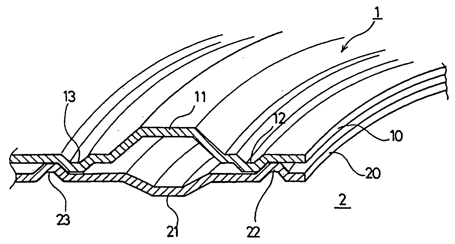
[0049] In the first embodiment as shown in FIGS. 1 and 2, the abutment between the first inner peripheral side sub-bead 12 and the second inner peripheral side sub-bead 22 and the abutment between the first outer peripheral side sub-bead 13 and the second outer peripheral side sub-bead 23 are carried out, respectively, such that the respective side portions of mutually inward projecting beads abut against each other.

[0050] While the first main bead 11 and the second main bead 21 normally have different shapes (including sizes), they may be the same shape. When the first main bead 11 and the second main bead 21 have the same shape, since there may be a temperature difference between the first metal base plate 10 and the second metal base plate 20, the sub-beads 12, 13, 22, 23 mainly play a role for mutually positioning the metal base plates 10 and 20 though there is deformation constraint of the main beads 11, 21.

[0051] In FIG. 1, the first main bead11 and the second main bead 21 ha...

second embodiment

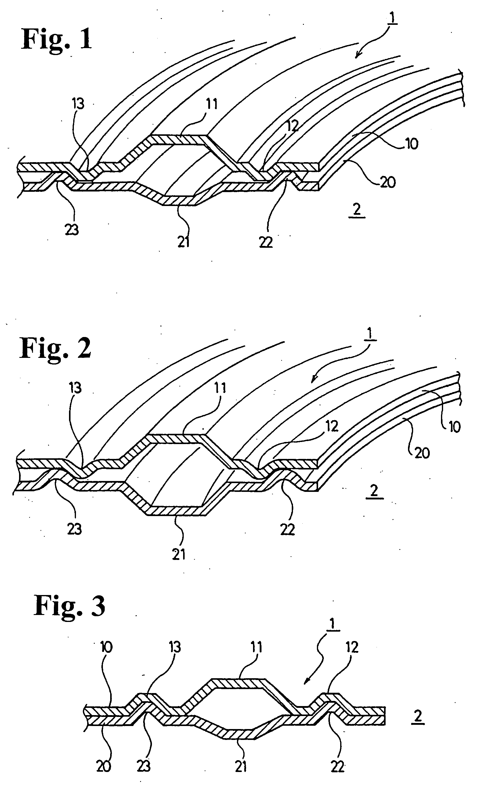
[0052] Also, in a second embodiment as shown in FIGS. 3 and 4, a first inner peripheral side sub-bead 12 abuts against a second inner peripheral side sub-bead 22, and a first outer peripheral side sub-bead 13 abuts against a second outer peripheral side sub-bead 23. The abutments are made such that one bead enters the other bead to fit each other.

[0053] In FIG. 3, a first main bead 11 and a second main bead 21 and respective sub-beads 12, 13, 22, 23 are made in a trapezoidal shape. In FIG. 4, the first main bead 11 and the second main bead 21 and the respective sub-beads 12, 13, 22, 23 are made in a circular arc shape.

third embodiment

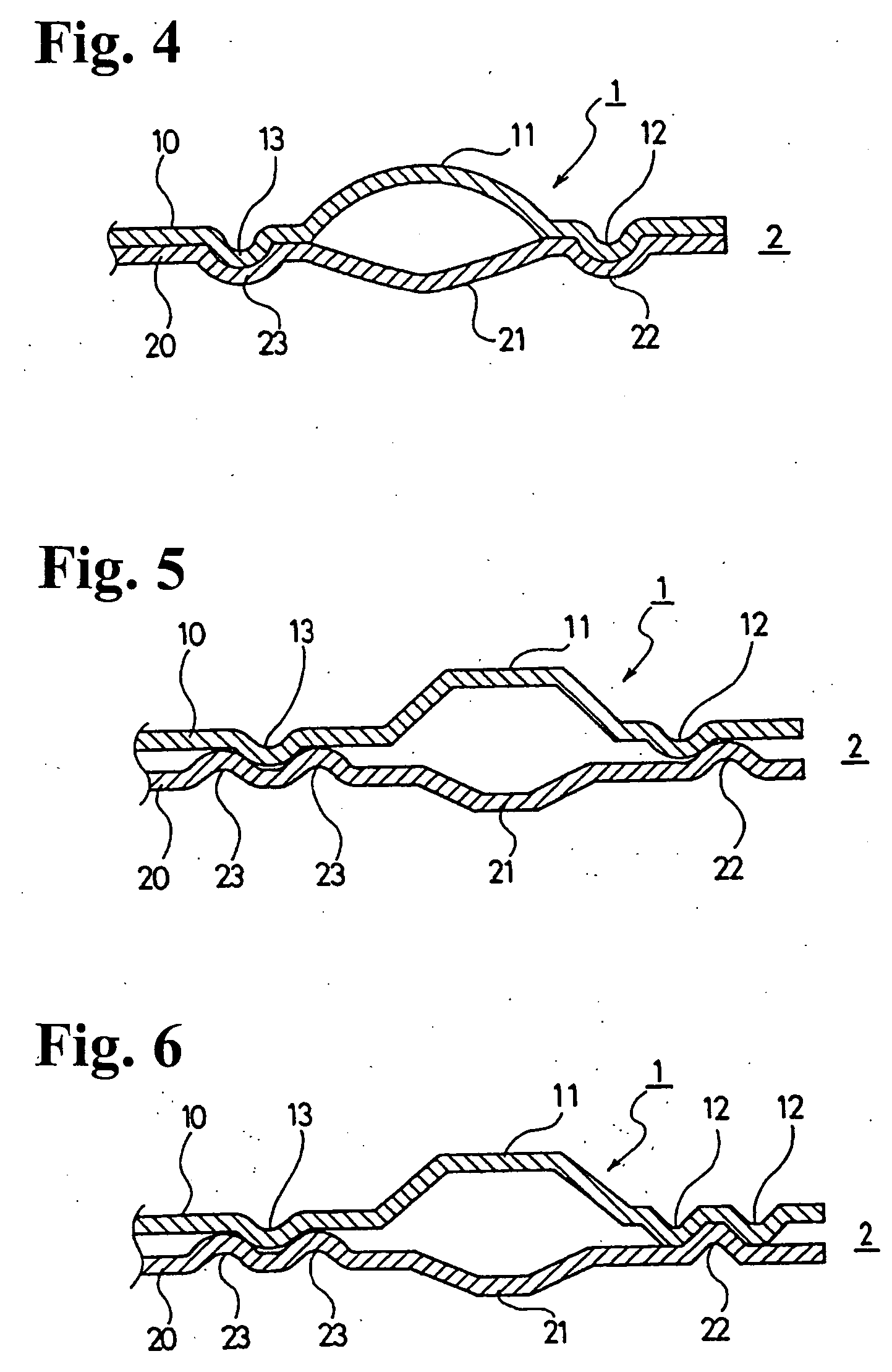
[0054] In the invention as shown in FIGS. 5 and 6, at least one of a first inner peripheral side sub-bead 12, a second inner peripheral side sub-bead 22, a first outer peripheral side sub-bead 13 and a second outer peripheral side sub-bead 23 is formed of a plurality of beads.

[0055] In FIG. 5, the second outer peripheral side sub-bead is formed of two beads 23 so that the first outer peripheral side sub-bead 13 is sandwiched therebetween. In FIG. 6, further, the first inner peripheral side sub-bead is formed of two beads 12 so that the second inner peripheral side sub-bead 22 is sandwiched therebetween. The number of the sub-beads may be two to three, if there is enough room to provide. There is no specific limitation.

[0056] In all structures of FIGS. 1 through 6, the sub-beads 12, 13, 22, 23 may be provided around the whole circumference in the circumferential direction, or may be discontinuously or intermittently provided. With the length and the position of the sub-beads, the ma...


PUM


Abstract

A metal gasket is formed by first and second metal base plates. The first metal base plate has a first main bead, and first outer and inner sub-bead sections formed outside and inside the first main bead and projecting outwardly in a direction opposite to the first main bead. The second metal base plate has a second main bead, and second outer and inner sub-bead sections formed outside and inside the second main bead and projecting outwardly in a direction opposite to the second main bead. A distance between the second outer and inner sub-bead sections is greater than that between the first outer and inner sub-bead sections. When the first and second metal base plates are assembled, the second outer and inner sub-bead sections entirely sandwich the first outer and inner sub-bead sections therebetween to substantially abut against each other at side peripheries thereof.

Description

CROSS-REFERENCE TO RELATED APPLICATION [0001] This is a continuation application of Ser. No. 10 / 804,070 filed on Mar. 19, 2004.BACKGROUND OF THE INVENTION AND RELATED ART STATEMENT [0002] The invention relates to a metal gasket, such as a cylinder head gasket, to be sandwiched between two members, for example a cylinder head and a cylinder block, of an internal combustion engine to seal therearound. [0003] In case joint surfaces of a cylinder head and a cylinder block (cylinder body) of a vehicle are sealed, combustion gas, cooling water, lubricating oil and the like are sealed by sandwiching a cylinder head gasket therebetween. [0004] To meet demands of reducing weight of an engine and a production cost, a cylinder head gasket has been changed to a simple structural cylinder head gasket formed of one or two metal base plates from a metal laminate type gasket including a plurality of metal base plates. Therefore, the constituent plates become one or two, usable materials are limited...

Claims


Application Information

Patent Timeline
IPC IPC(8): F02F11/00F16J15/08
CPCF02F11/002F16J15/0825F16J2015/085F16J15/08
Inventor SUEDA, MASAKAZU
Owner ISHIKAWA GASKET CO LTD
Why Eureka
Try Eureka