Metal gasket
a technology of metal gaskets and sealing devices, applied in the direction of engine sealing, machine/engine, engine sealing arrangements, etc., can solve the problems of limited design freedom, limited use of materials, and limited type and number of sealing devices, and achieve the effect of easy adjustment of the strength of the binding for
- Summary
- Abstract
- Description
- Claims
- Application Information
AI Technical Summary
Benefits of technology
Problems solved by technology
Method used
Image
Examples
first embodiment
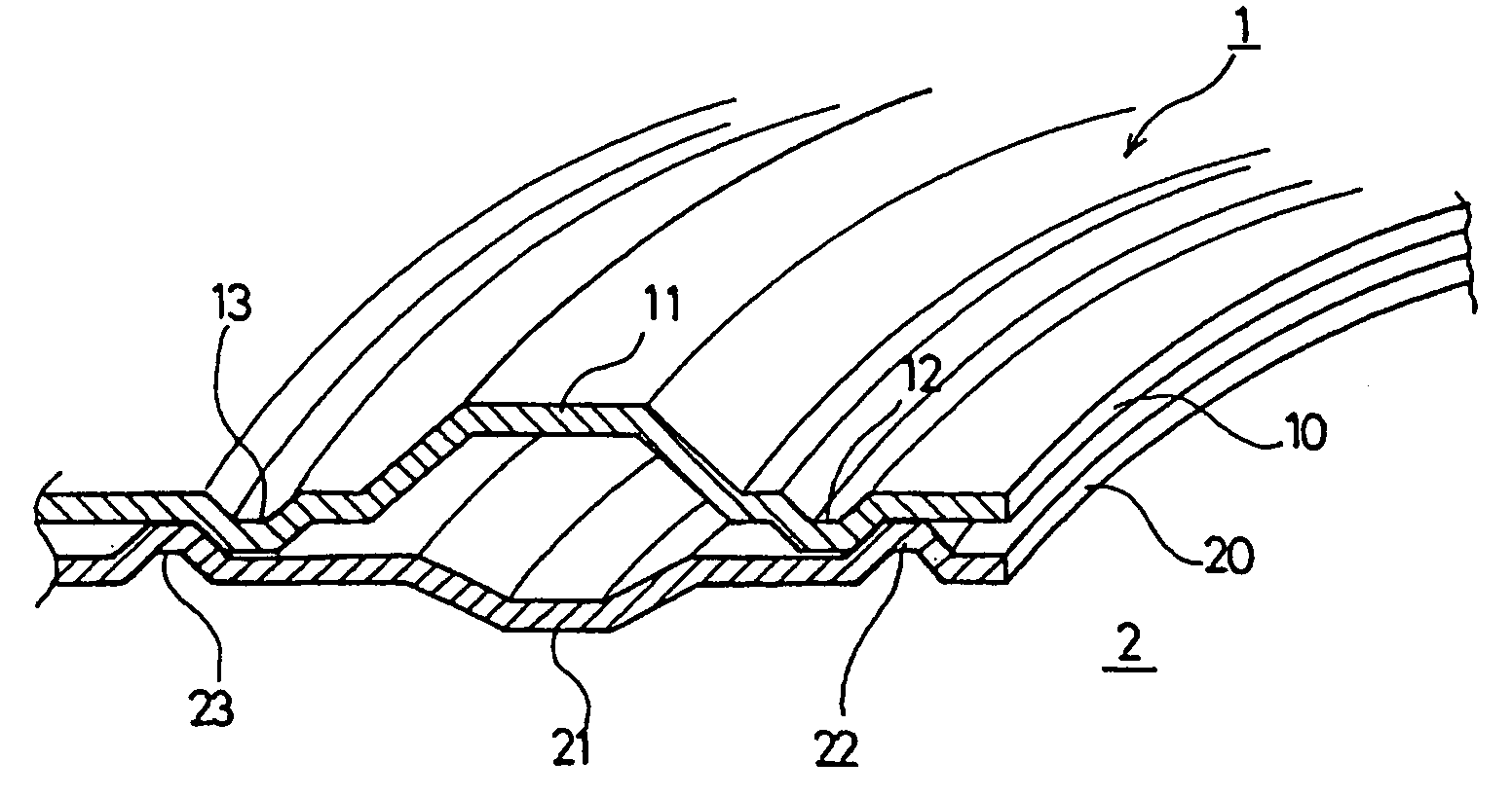
[0049]In the first embodiment as shown in FIGS. 1 and 2, the abutment between the first inner peripheral side sub-bead 12 and the second inner peripheral side sub-bead 22 and the abutment between the first outer peripheral side sub-bead 13 and the second outer peripheral side sub-bead 23 are carried out, respectively, such that the respective side portions of mutually inward projecting beads abut against each other.
[0050]While the first main bead 11 and the second main bead 21 normally have different shapes (including sizes), they may be the same shape. When the first main bead 11 and the second main bead 21 have the same shape, since there may be a temperature difference between the first metal base plate 10 and the second metal base plate 20, the sub-beads 12, 13, 22, 23 mainly play a role for mutually positioning the metal base plates 10 and 20 though there is deformation constraint of the main beads 11, 21.
[0051]In FIG. 1, the first main bead 11 and the second main bead 21 have ...
second embodiment
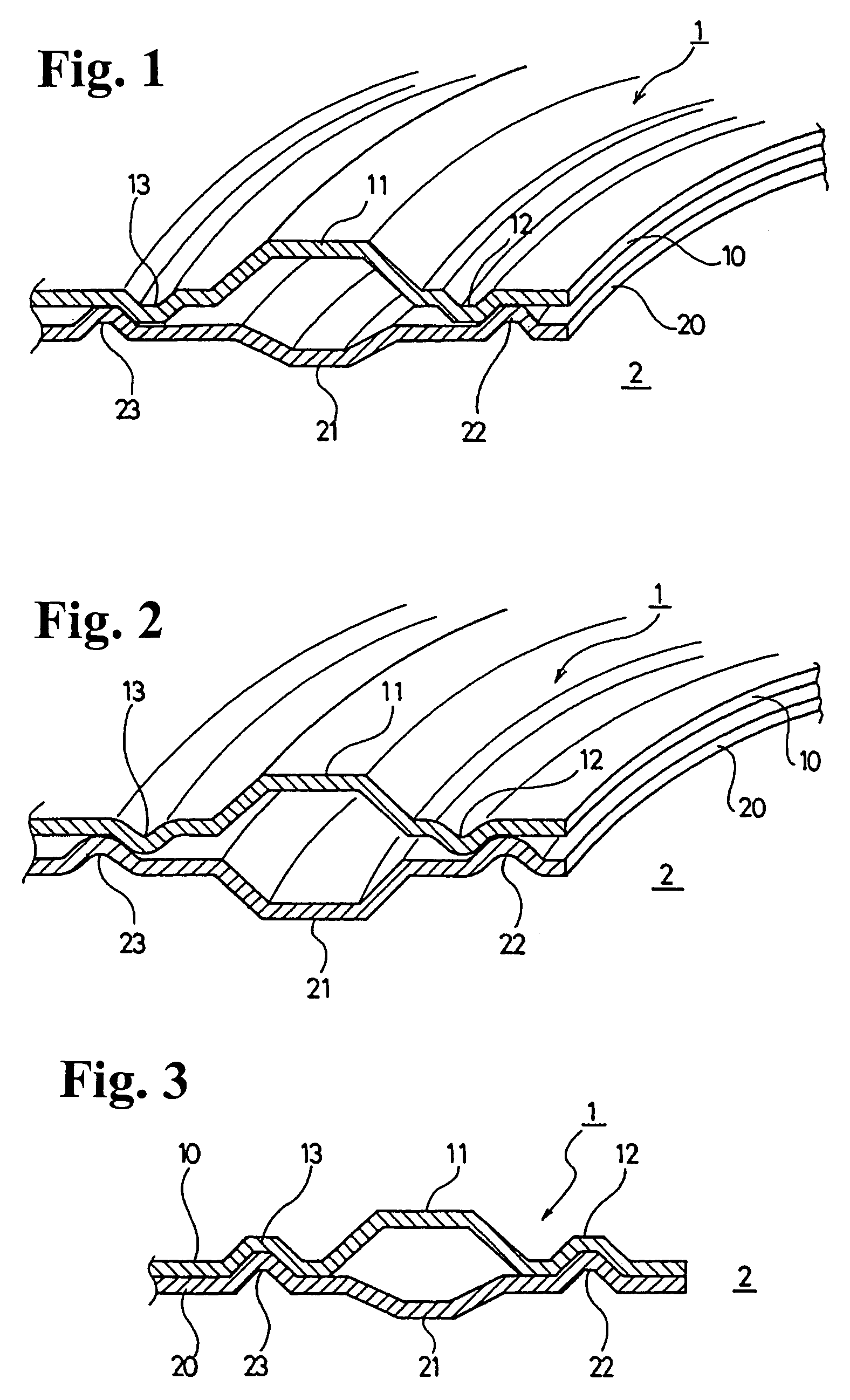
[0052]Also, in a second embodiment as shown in FIGS. 3 and 4, a first inner peripheral side sub-bead 12 abuts against a second inner peripheral side sub-bead 22, and a first outer peripheral side sub-bead 13 abuts against a second outer peripheral side sub-bead 23. The abutments are made such that one bead enters the other bead to fit each other.
[0053]In FIG. 3, a first main bead 11 and a second main bead 21 and respective sub-beads 12, 13, 22, 23 are made in a trapezoidal shape. In FIG. 4, the first main bead 11 and the second main bead 21 and the respective sub-beads 12, 13, 22, 23 are made in a circular arc shape.
third embodiment
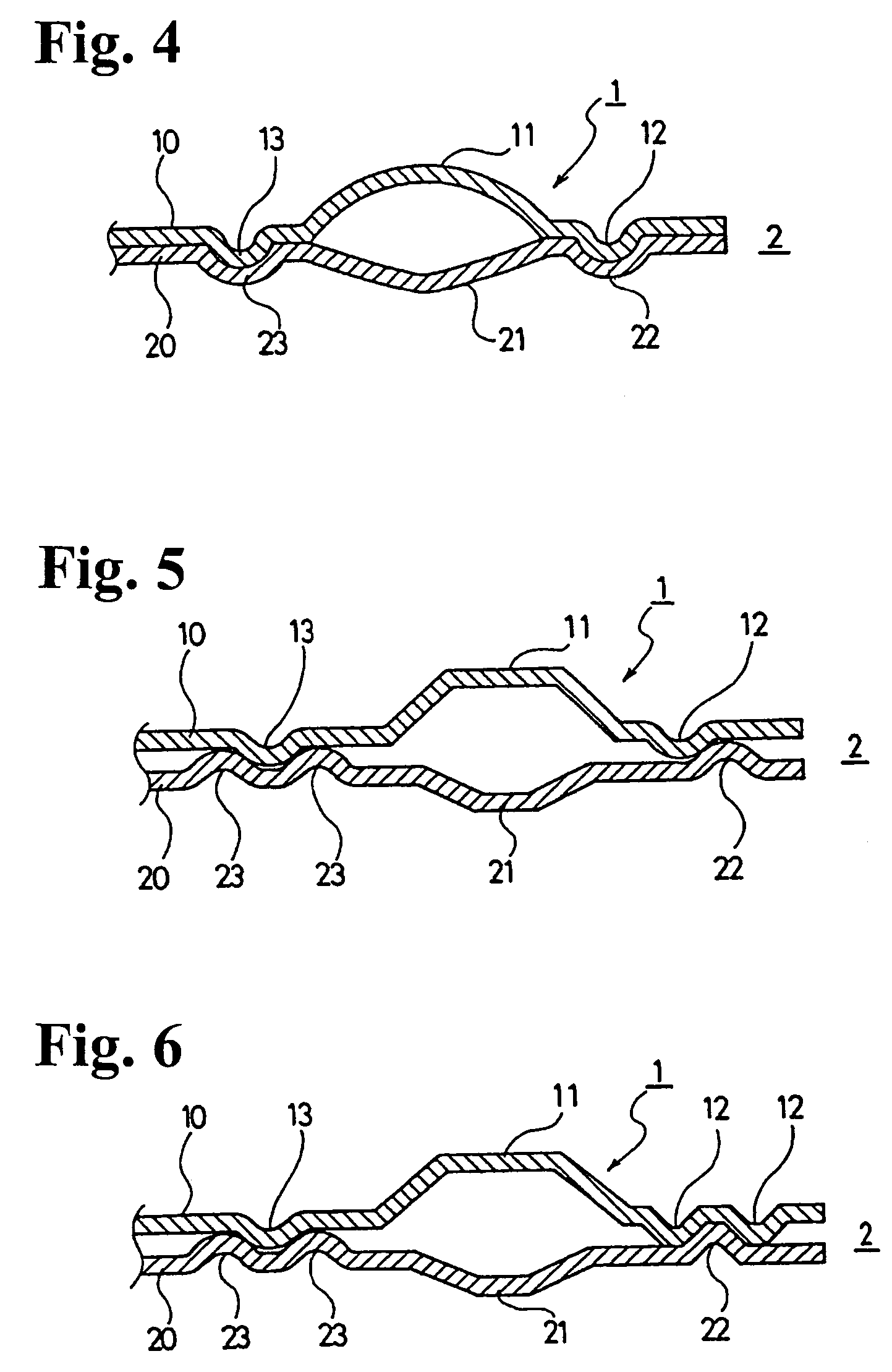
[0054]In the invention as shown in FIGS. 5 and 6, at least one of a first inner peripheral side sub-bead 12, a second inner peripheral side sub-bead 22, a first outer peripheral side sub-bead 13 and a second outer peripheral side sub-bead 23 is formed of a plurality of beads.
[0055]In FIG. 5, the second outer peripheral side sub-bead is formed of two beads 23 so that the first outer peripheral side sub-bead 13 is sandwiched therebetween. In FIG. 6, further, the first inner peripheral side sub-bead is formed of two beads 12 so that the second inner peripheral side sub-bead 22 is sandwiched therebetween. The number of the sub-beads may be two to three, if there is enough room to provide. There is no specific limitation.
[0056]In all structures of FIGS. 1 through 6, the sub-beads 12, 13, 22, 23 may be provided around the whole circumference in the circumferential direction, or may be discontinuously or intermittently provided. With the length and the position of the sub-beads, the magnit...
PUM
 Abstract
Description
Claims
Application Information
 - R&D
- Intellectual Property
- Life Sciences
- Materials
- Tech Scout
- Unparalleled Data Quality
- Higher Quality Content
- 60% Fewer Hallucinations
Browse by: Latest US Patents, China's latest patents, Technical Efficacy Thesaurus, Application Domain, Technology Topic, Popular Technical Reports.
© 2025 PatSnap. All rights reserved.Legal|Privacy policy|Modern Slavery Act Transparency Statement|Sitemap|About US| Contact US: help@patsnap.com


