
Chocking apparatus

a technology of shock absorber and shock absorber, which is applied in the direction of vehicle maintenance, braking system, refusal gathering, etc., can solve the problems of unintentional displacement of vehicles that are only blocked with their parking brakes, heavy truck load, and high risk of accidents, so as to prevent unintentional displacement of road freight vehicles. efficient and securely

Inactive Publication Date: 2006-07-06
ERIKSSON SA
View PDF7 Cites 12 Cited by
  • Summary
  • Abstract
  • Description
  • Claims
  • Application Information

AI Technical Summary

Benefits of technology

[0006] The invention eliminates the above discussed disadvantages in an efficient and appropriate manner. A general object of the invention is to provide a practically useful solution to the problem of efficiently and securely preventing unintentional displacement of a road freight vehicle in association with loading and / or unloading at a loading dock.
[0007] A basic object of the invention is therefore to provide an improved apparatus that effects reliable blocking or restraining of a vehicle at a loading dock and Eat is simultaneously simple to handle and interferes minimally with the loading dock as well as with the truck parking surface. Briefly, in accordance with the invention, this is achieved by means of a telescoping arm that at one end thereof is supported so as to be stationary but pivotal about two axes and that at the opposite end is provided with an engagement means for effecting a blocking connection between a vehicle and a loading dock area. At the same time as the stationary end may be provided at a safe position where it is practically completely out of the way when it comes to e.g. snow clearance and risk of collision, the capability of pivotal adjustment and the telescoping design of the arm make it possible to easily maneuver the engagement means into blocking engagement from the outside of the vehicle.
[0010] According to a practical embodiment of the invention, the arm is supported in the area of a front surface of the loading dock that faces the road freight vehicle and is pivotal about a vertical and a horizontal axis. This design provides for a simple maneuverability and at the same tine, the arm may be supported below the loading surface of the loading dock and in the applicable case even under the same, just inside the front surface.
[0012] In a practical embodiment, the arm has two tubes or pipes that are telescopically displaceable in relation to each other. A piston-cylinder assembly is received in one of the tubes so that its cylinder and its piston rod are connected to one each of the tubes. In this way, a simple maneuverability of the apparatus is provided for.
[0013] At a position between its ends, the arm is connected to a support device that permits simple pivoting of the apparatus about the axes for positioning it in a blocking position and in an inactive position, respectively. The support device may consist of a support leg that is adjustable in height to permit pivoting of the arm about a horizontal axis and that carries a pivoting support wheel for allowing pivoting of the arm about a vertical axis. Alternatively, the support device may consist of a balancing spring that engages the arm to permit balanced-out pivoting of the arm about both axes.
[0014] Further possibilities of adaption and safety are achieved by providing an adjustable side stop on the engagement means, said side stop being intended to engage the side of a vehicle wheel.

Problems solved by technology

There is a very serious risk of accidents occurring in association with the loading and unloading of trucks and tilers, when such loading / unloading is carried out by means of fork-lift trucks at a loading dock or loading bay.
The truck and its load often weighs several tons and there is an apparent risk that a vehicle that is only blocked with its parking brake will be displaced just in association with driving onto the truck bed or the ramp.
Naturally, the risk of sliding is greater during wintertime when the vehicle wheels may be positioned on snow or ice.
Such an unintentional displacement of a truck when driving onto it may have very serious consequences, since there is a risk of the fork-lift truck overturning or partly or completely falling down between the loading dock and the vehicle.
Such traditional chocking suffers from many drawbacks.
A chock that is not properly driven in under the wheel may easily come loose and simply be pushed ahead in front of the wheel.
Moreover, no immediate indication is given to the forklift driver, neither regarding the fact that chocking has really been performed nor whether it has been properly performed.
It is also known to secure or restrain vehicles by means of straps or chains, but these methods are both complex and unsafe.
The first mentioned variant inevitably causes problems in association with snow clearance work etc.
Furthermore, it may easily become blocked or even damaged in case the road freight vehicle is maneuvered so that it assumes an incorrect position on the device.
The last mentioned variant involves very high costs, partly on account of the fact that its design is relatively complex and expensive and partly since it requires that an accommodating space is formed in the truck parking surface and is appropriately drained.
Finally U.S. Pat. No. 5,743,697 describes a wheel chocking apparatus that is indeed supported at the front of the loading dock, facing the vehicle, but that likewise, in all positions, interferes essentially with the driveway or truck parking surface and is an obstacle to snow clearance and other maintenance work at the parking surface.
It is moreover intended to be introduced between the wheels of one wheel axle of the road freight vehicle in association with backing the vehicle up toward the loading dock Since it has a fixed width, it requires high precision during backing, and in addition thereto it does not permit any substantive variations in the axle width or track of the road freight vehicles.

Method used


Image

  • Chocking apparatus
  • Chocking apparatus
  • Chocking apparatus

Examples


Embodiment Construction

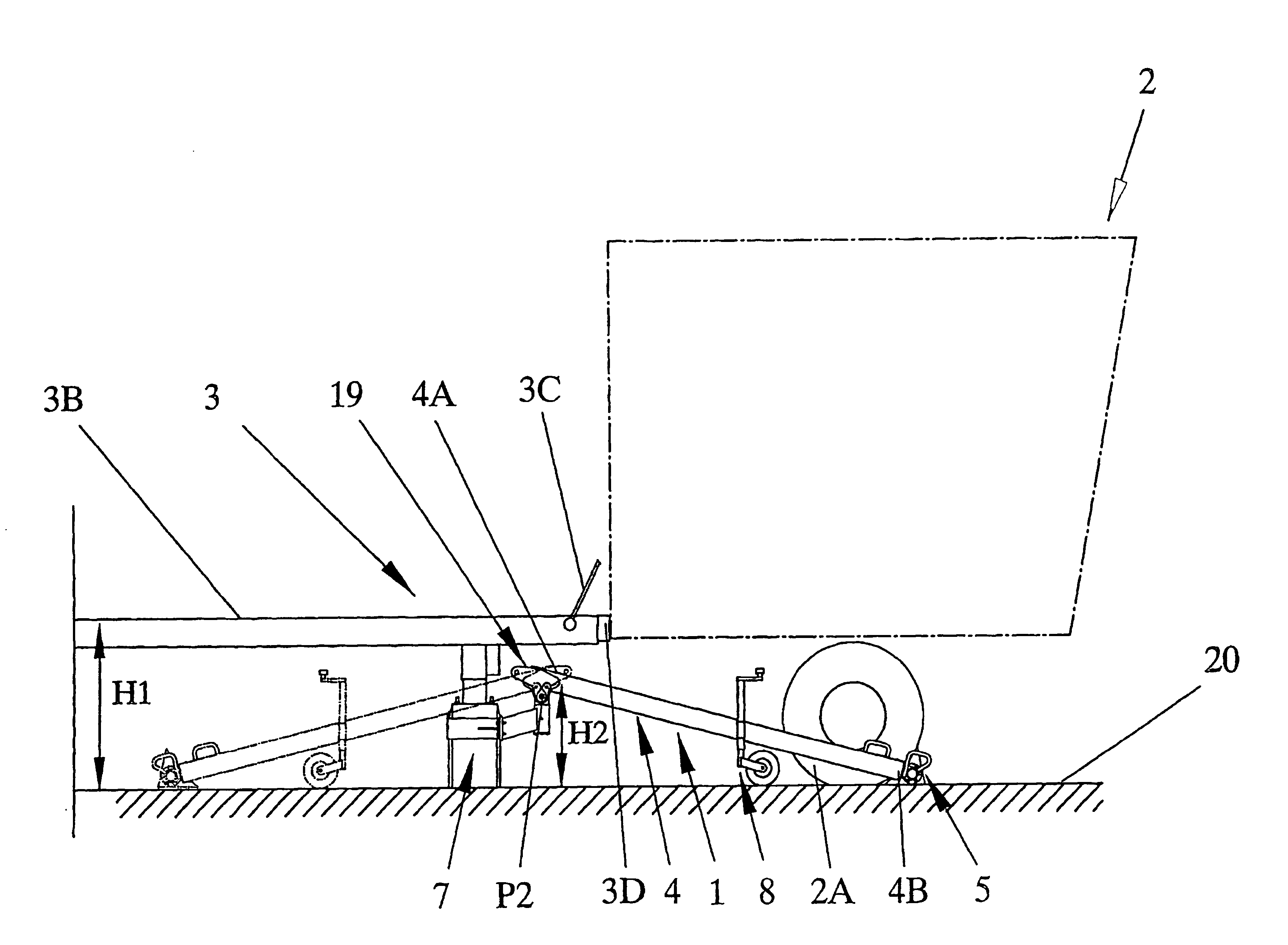
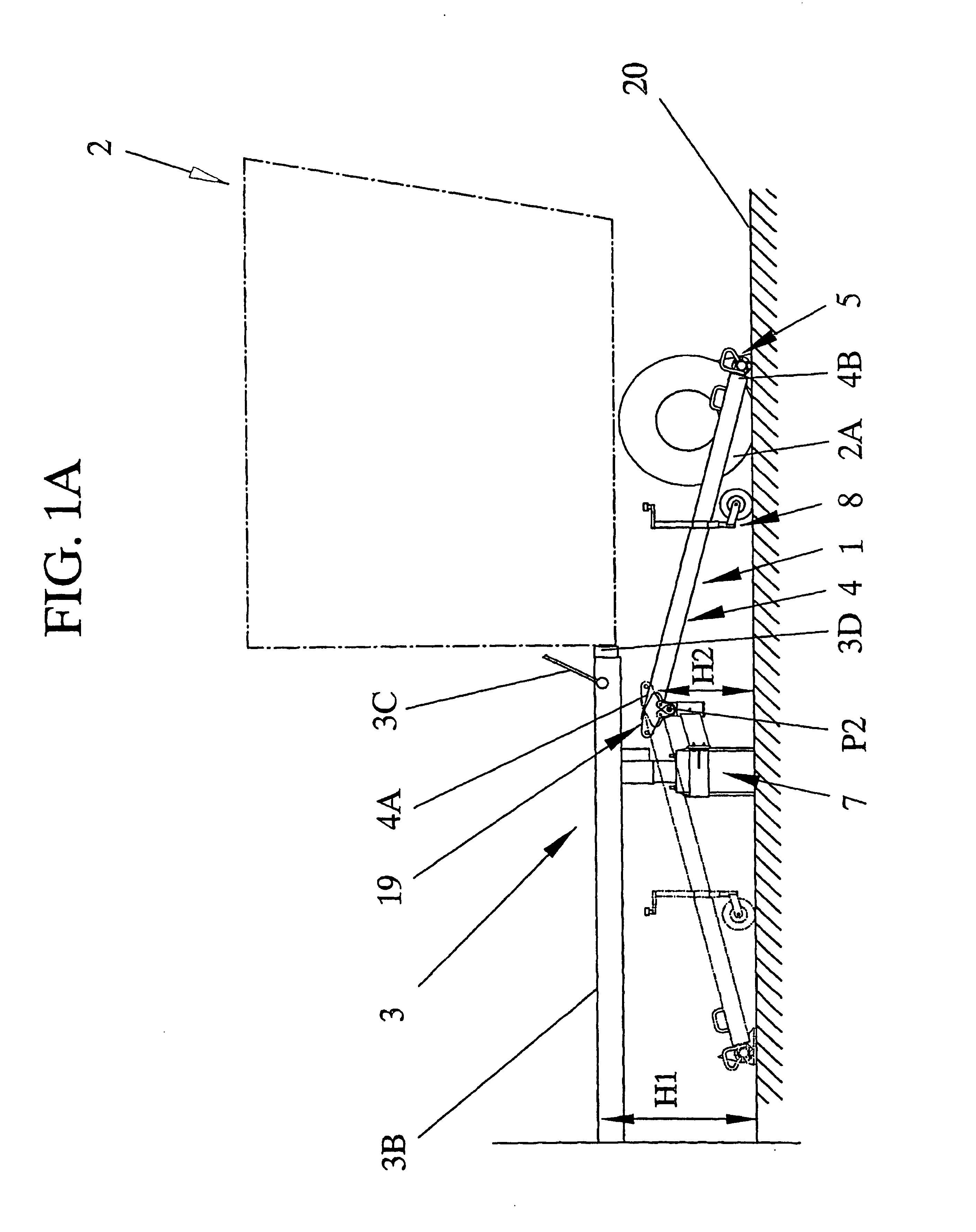
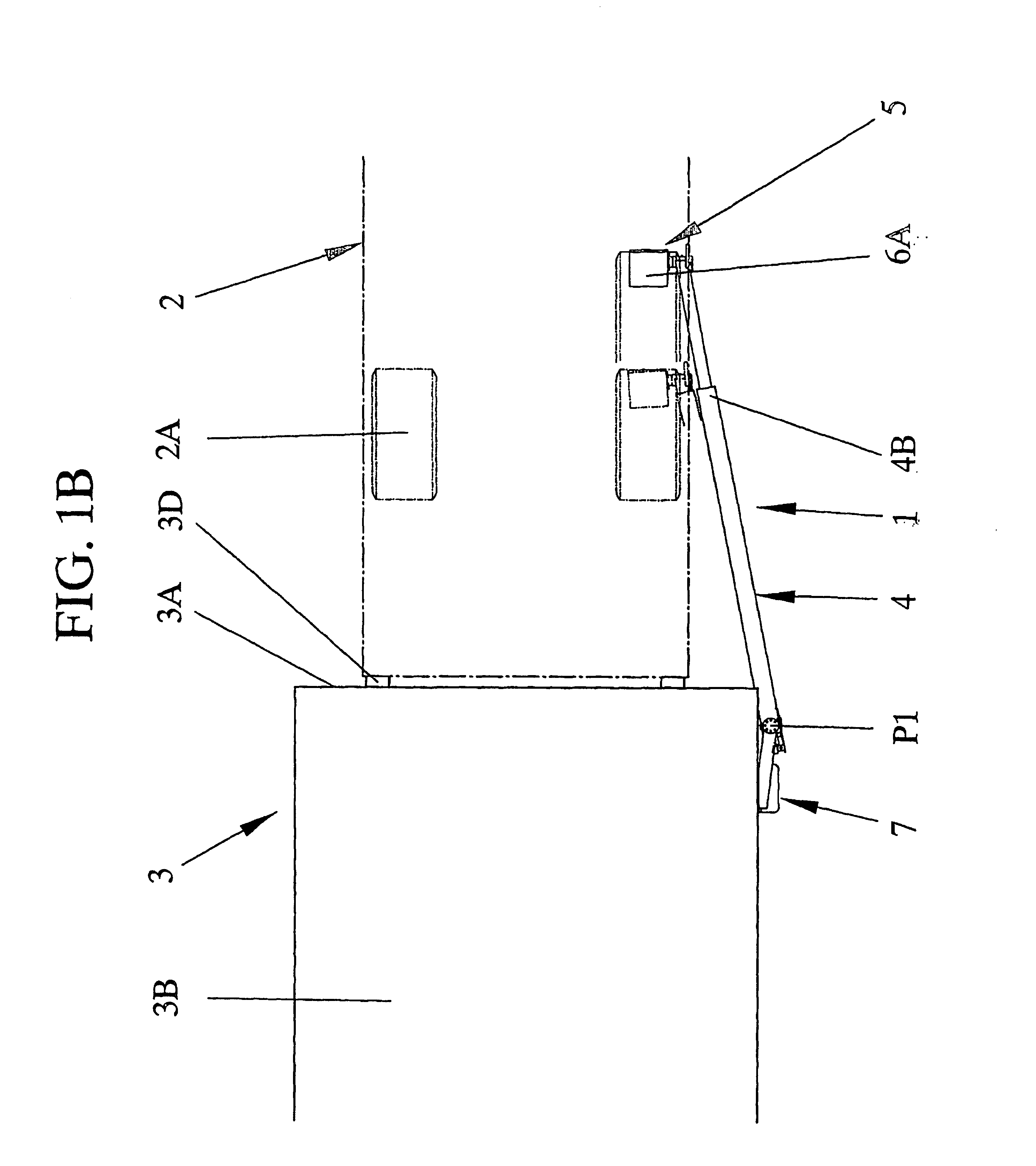
[0026] Referring to the drawing figures the basic principles of the invention will now be described by means of embodiments thereof, and at the same time, the differences in comparison with the conventionally employed technique will be clarified.

[0027] The invention and its basic principles will initially be described with reference to the partly schematical illustrations of FIGS. 1A-B and 2A-B. Specifically, they illustrate a presently preferred embodiment of a chocking apparatus 1 according to the invention, mounted in the area of a loading dock 3. On a surface 20 where trucks are to be parked, here also referred to as a truck parking surface or driveway, a very schematically illustrated road freight vehicle 2 has been backed up towards the loading dock 3 that is normally provided with rubber bumpers 3D for taking up forces from possible collisions caused by backing. In order to bridge the distance between the loading surface 3B of the loading dock 3 and the loading bed, not illu...


PUM


Abstract

An apparatus (1) for reliably blocking a vehicle (2) at a loading dock (3) includes a telescopic arm (4) that at one end (4A) is supported so as to be stationary but is pivotal about two axes (P1, P2) and that at the opposite end (4B) is provided with an engagement element (5) for effecting a blocking connection between the vehicle and the area of a loading dock. At the same time as the stationary end maybe provided at a safe position where it is practically completely out of the way when it comes to e.g. snow clearance and risk of being run into, the capability of pivotal movement and the telescopic design of the arm makes it possible to easily maneuver the engagement element into a blocking or restraining engagement from the outside of the vehicle.

Description

TECHNICAL FIELD [0001] The invention relates generally to apparatuses that serve to prevent unintentional displacement of road freight vehicles or trucks and their load carriers, trailers or semi-trailers in connection with loading and unloading at a loading dock or the like. BACKGROUND [0002] There is a very serious risk of accidents occurring in association with the loading and unloading of trucks and tilers, when such loading / unloading is carried out by means of fork-lift trucks at a loading dock or loading bay. In such cases, a fork-lift truck may be driven onto the loading bed of the truck or trailer through a swingable ramp or leveller that is normally anchored at the loading dock. The truck and its load often weighs several tons and there is an apparent risk that a vehicle that is only blocked with its parking brake will be displaced just in association with driving onto the truck bed or the ramp. Naturally, the risk of sliding is greater during wintertime when the vehicle wh...

Claims


Application Information

Patent Timeline
Patent Type & Authority Applications(United States)
IPC IPC(8): B60S9/02B60T3/00B65G69/00
CPCB60T3/00B65G69/005
Inventor ERIKSSON
Owner ERIKSSON SA
Learn More