Electronically steerable sector antenna

a technology of electromagnetic steering and antennas, applied in the direction of antennas, antenna details, substation equipment, etc., can solve the problems of not meeting the expectations of such systems, achieving adequate rf coverage at a desired data throughput, and increasing the equipment cost of each additional access point, so as to achieve the effect of improving the data rate of the channel for communicating wireless data and greater signal strength

Inactive Publication Date: 2006-07-06
MICROSOFT TECH LICENSING LLC
View PDF19 Cites 22 Cited by
  • Summary
  • Abstract
  • Description
  • Claims
  • Application Information

AI Technical Summary

Benefits of technology

[0007] The present invention achieves a substantially greater signal strength when communication with another device over a wireless network (compared to a conventional omni-directional antenna), by selective steering the antenna transmitting or receiving data so that the direction in which data are communicated by the steerable antenna is generally directed toward the other device in the link. In this manner, the data rate of the channel for communicating wireless data will be substantially improved compared to a more conventional wireless network in which the RF signal is transmitted and received in all directions.

Problems solved by technology

As an increasing number of computer users install wireless networks that meet the Institute of Electrical and Electronics Engineers (IEEE) 802.11 specifications in their homes and workplaces, it has become apparent that the performance (i.e., range and data rate) of such systems often fails to meet their expectations.
Structures built of stone or brick, or which contain blocking interior elements, such as a fireplace or metal walls, often have problems with achieving adequate RF coverage at a desired data throughput.
Typically, the only way to achieve the desired coverage and throughput in an office or home is to add more access points so that the distance and intervening structural elements between the access points and the clients devices is reduced, which means higher wiring costs to run Ethernet cabling to the additional access points and greater equipment costs for each added access point.
Increasing transmitter power is typically not an option due to regulatory limitations and / or because significantly increased power consumption is not acceptable for a battery powered side of a link.
However, the direction in which the RF energy needs to be transmitted or received is not fixed in most wireless system, because a fixed access point must be able to maintain communications with moving client devices, or communicate with client devices that are located at different positions scattered around the access point.
Unfortunately, these systems are typically large and very expensive, and consequently, have generally not appeared in consumer products.
This technology is also beginning to appear in commercial access points intended for installation in large scale commercial applications, such as at airports or in universities, but suitable systems still cost thousands of dollars.

Method used


Image

  • Electronically steerable sector antenna
  • Electronically steerable sector antenna
  • Electronically steerable sector antenna

Examples


Embodiment Construction

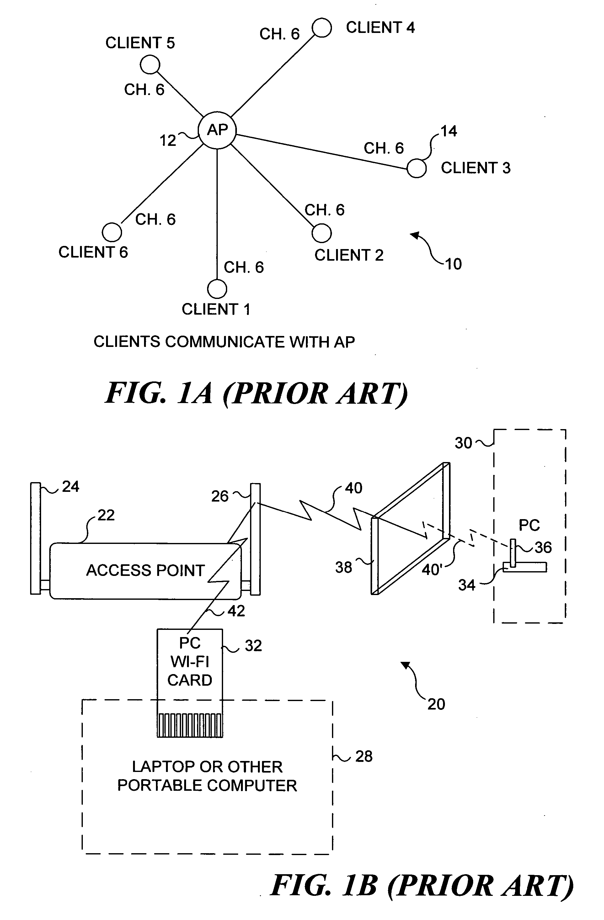
[0024] As briefly discussed above, in the Background of the Invention, conventional wireless networks often experience significant problems in providing acceptable signal strength and data rate. A typical wireless network 10 is illustrated in FIG. 1A (Prior Art). In this wireless network, an access point 12 is coupled to a plurality of client devices 14 and communicates bidirectionally with the client devices using transceivers conforming to the IEEE 802.11(a, b, or g) specifications. As is often the case, client devices 14 are distributed around access point 12 in various positions and at various distances. Indeed, client devices are often mobile and therefore, their position may frequently change in regard to access point 12. For this reason, most client devices and access points are provided with one or more omni-directional antennas (not shown in this Figure) to ensure that the RF signal being propagated between the client devices and the access point is receivable from any dire...


PUM


Abstract

An electronically steerable antenna system includes a plurality of panels that are coupled together to form an N-sided polygon. Each panel includes a plurality of microstrip conductor patches forming a phased array antenna. In a first embodiment that includes beam steering, each panel can selectively transmit or receive in a direction that is either perpendicular to the panel, or to the left or right of perpendicular, depending upon relative delay line lengths applied to the left and right antennas. A second embodiment omits the beam steering capability for each panel and simply enables only one of the N different panels to be employed for transmitting or receiving a radiofrequency signal in a direction perpendicular to the panel. PIN diodes are preferably used for selecting the panel that is active, and in the first embodiment, for selecting the delay lines used.

Description

FIELD OF THE INVENTION [0001] The present invention generally pertains to a multi-panel antenna that is able to selectively transmit and receive a radio frequency (RF) signal in a desired direction, and more specifically, to a multi-panel antenna that includes an electronic switching network for selectively activating one of the panel antennas to control a direction in which an RF signal is transmitted or received by the multi-panel antenna. cl BACKGROUND OF THE INVENTION [0002] As an increasing number of computer users install wireless networks that meet the Institute of Electrical and Electronics Engineers (IEEE) 802.11 specifications in their homes and workplaces, it has become apparent that the performance (i.e., range and data rate) of such systems often fails to meet their expectations. Structures built of stone or brick, or which contain blocking interior elements, such as a fireplace or metal walls, often have problems with achieving adequate RF coverage at a desired data th...

Claims


Application Information

Patent Timeline
Patent Type & Authority Applications(United States)
IPC IPC(8): H01Q3/12H04M1/00
CPCH01Q1/007H01Q1/2258H01Q3/24H01Q3/2682H01Q3/36H01Q21/20
Inventor RANTA, CRAIG STEVENYIN, QIN-YEJIANG, YAN-SHENG
Owner MICROSOFT TECH LICENSING LLC
Why Eureka
Try Eureka