
Backlight module and liquid crystal display using the same

Inactive Publication Date: 2006-07-06
INNOLUX SISPLAY
View PDF5 Cites 4 Cited by
  • Summary
  • Abstract
  • Description
  • Claims
  • Application Information

AI Technical Summary

Benefits of technology

[0008] In one preferred embodiment, a backlight module for a liquid crystal display device includes a light guide plate and a point light source adjacent to the light guide plate. A horizontal central axis of the point light source and a horizontal central axis of the light guide plate are on a same plane. The backlight module can provide uniform light.
[0009] In another embodiment, a liquid crystal display device includes a liquid crystal display panel and a backlight module for illuminating the liquid crystal panel. The backlight module includes a light guide plate and a point light source adjacent to the light guide plate. A horizontal central axis of the point light source and a horizontal central axis of the light guide plate are on a same plane. The liquid crystal display device can provide a uniform display effect.

Problems solved by technology

Liquid crystal displays are commonly used as display devices for compact electronic apparatuses because they not only provide good quality images with little power, but also are very thin.

Method used


Image

  • Backlight module and liquid crystal display using the same
  • Backlight module and liquid crystal display using the same
  • Backlight module and liquid crystal display using the same

Examples


first embodiment

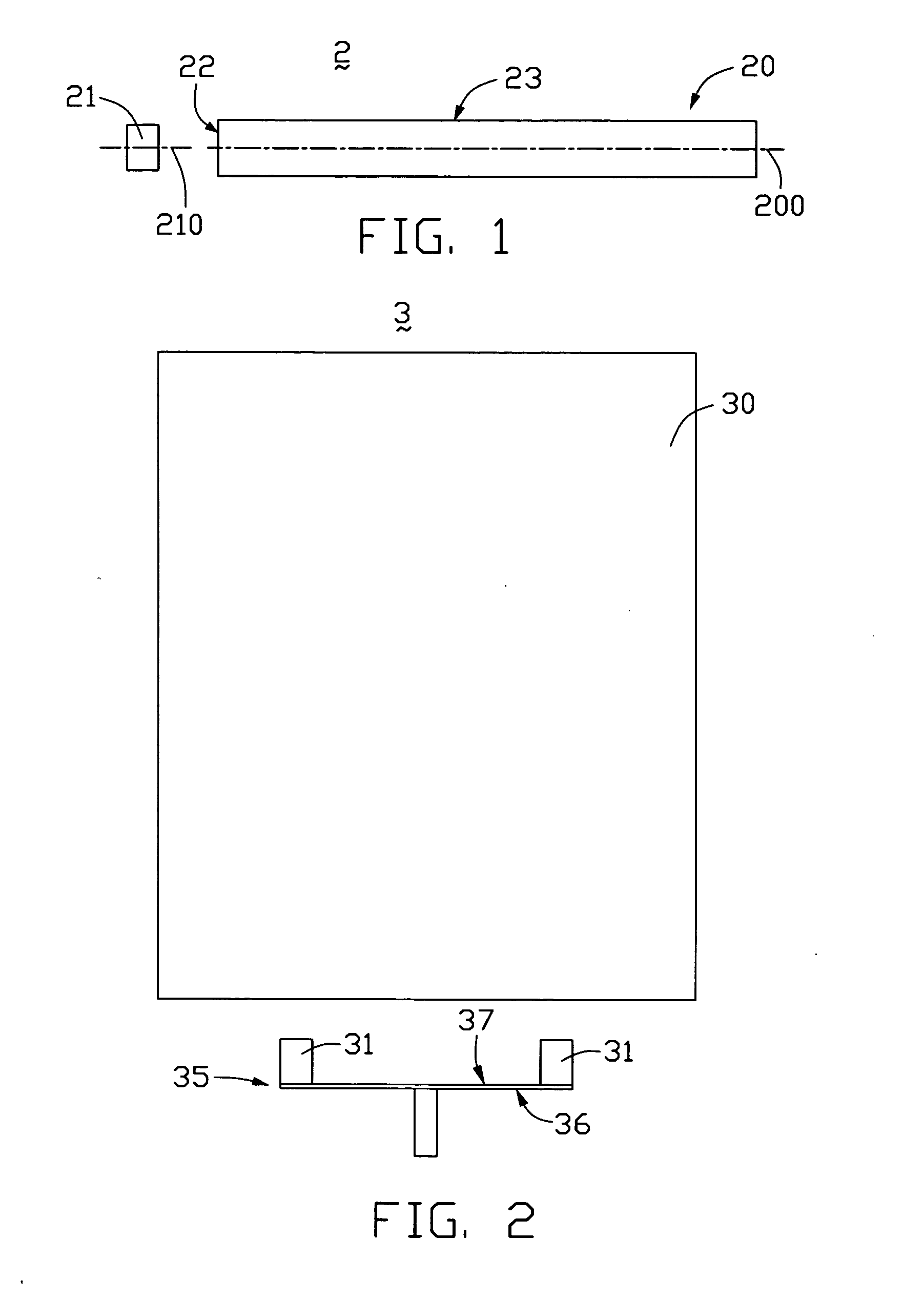
[0016] Referring to FIG. 1, a backlight module 2 according to the present invention includes an LGP 20 and a point light source 21. The LGP 20 includes a light incident surface 22, and a light emitting surface 23 adjacent to the light incident surface 22. The point light source 21 is an LED 21 adjacent to the light incident surface 22. A horizontal central axis 210 of the LED 21 and a horizontal central axis 200 of the LGP 20 are on a same plane. A height of the LED 21 is less than a thickness of the LGP 20, and a distance between the LED 21 and LGP 20 is less than 1×10⁻⁴ meters.

[0017] Because the horizontal central axis 210 of the LED 21 and the horizontal central axis 200 of the LGP 20 are on the same plane, light beams from the point light source 21 enter the LGP 20 through the light incident surface 22 such that the brightness below the horizontal central axis 200 of the LGP 20 is the same as the brightness above the horizontal central axis 200 of the LGP 20. This enables the ba...

third embodiment

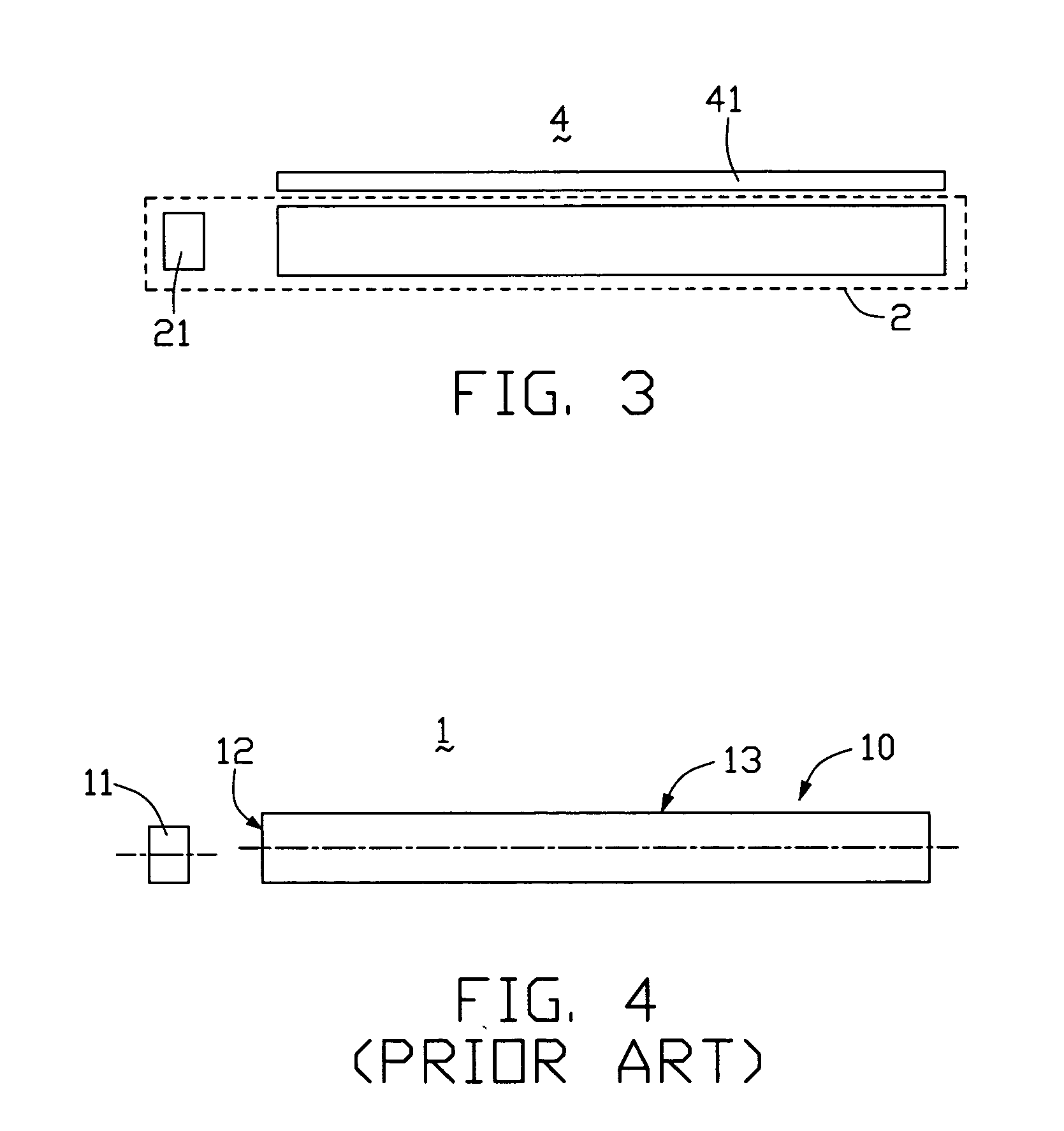
[0019] Referring to FIG. 3, a liquid crystal display device 4 according to the present invention includes a liquid crystal display panel 41 and the backlight module 2. Light beams from the point light source 21 enter the LGP 20, are emitted from the light emitting surface 23, and propagate to the liquid crystal panel 41. Liquid crystals (not shown) in the liquid crystal panel 41 are lit up by the light beams, whereby the liquid crystal display device 4 can clearly and uniformly display text and images.

[0020] In alternative embodiments, the height of the LED 21 or LEDs 31 can be the same as the thickness of the LGP 20, 30. The backlight module 2, 3 can further include a prism sheet, a diffusing sheet, a reflective sheet, and / or a polarizer.


PUM


Abstract

A liquid crystal display device (4) includes a liquid crystal display panel (41) and a backlight module (2) opposite to the liquid crystal display panel. The backlight module includes a light guide plate (20) and a point light source (21) adjacent to the light guide plate. A horizontal central axis (210) of the point light source and a horizontal central axis (200) of the light guide plate are on a same plane. The backlight module can further comprises a prism sheet, a diffusing sheet, a reflective sheet, and / or a polarizer. The liquid crystal display device can provide a uniform display effect.

Description

BACKGROUND OF THE INVENTION [0001] 1. Field of the Invention [0002] The present invention relates to a backlight module and a liquid crystal display (LCD) using the same. [0003] 2. General Background [0004] Liquid crystal displays are commonly used as display devices for compact electronic apparatuses because they not only provide good quality images with little power, but also are very thin. The liquid crystals in a liquid crystal display do not emit any light themselves. The liquid crystals have to be lit by a light source so as to clearly and sharply display text and images. Thus, a backlight module for an LCD is generally needed. [0005] A typical backlight module is shown in FIG. 4. The backlight module 1 includes a light guide plate (LGP) 10 and a light source 11. The LGP 10 includes a light incident surface 12, and a light emitting surface 13 adjacent to the light incident surface 12. The light source 11 is typically a light emitting diode (LED) adjacent to the light incident ...

Claims


Application Information

Patent Timeline
IPC IPC(8): F21V7/04
CPCG02B6/0013G02F1/133615
Inventor FANG, WU-HONG
Owner INNOLUX SISPLAY
Learn More