

Fixing unit, image forming apparatus, and image forming system
a technology of image forming apparatus and fixing unit, which is applied in the direction of electrographic process apparatus, ohmic-resistance heating, instruments, etc., can solve the problems of user etc. making an error in operation, malfunctioning or damaging the unit, and the function of the release member of the press contact will no longer be achieved
- Summary
- Abstract
- Description
- Claims
- Application Information
AI Technical Summary
Benefits of technology
Problems solved by technology
Method used
Image

Examples
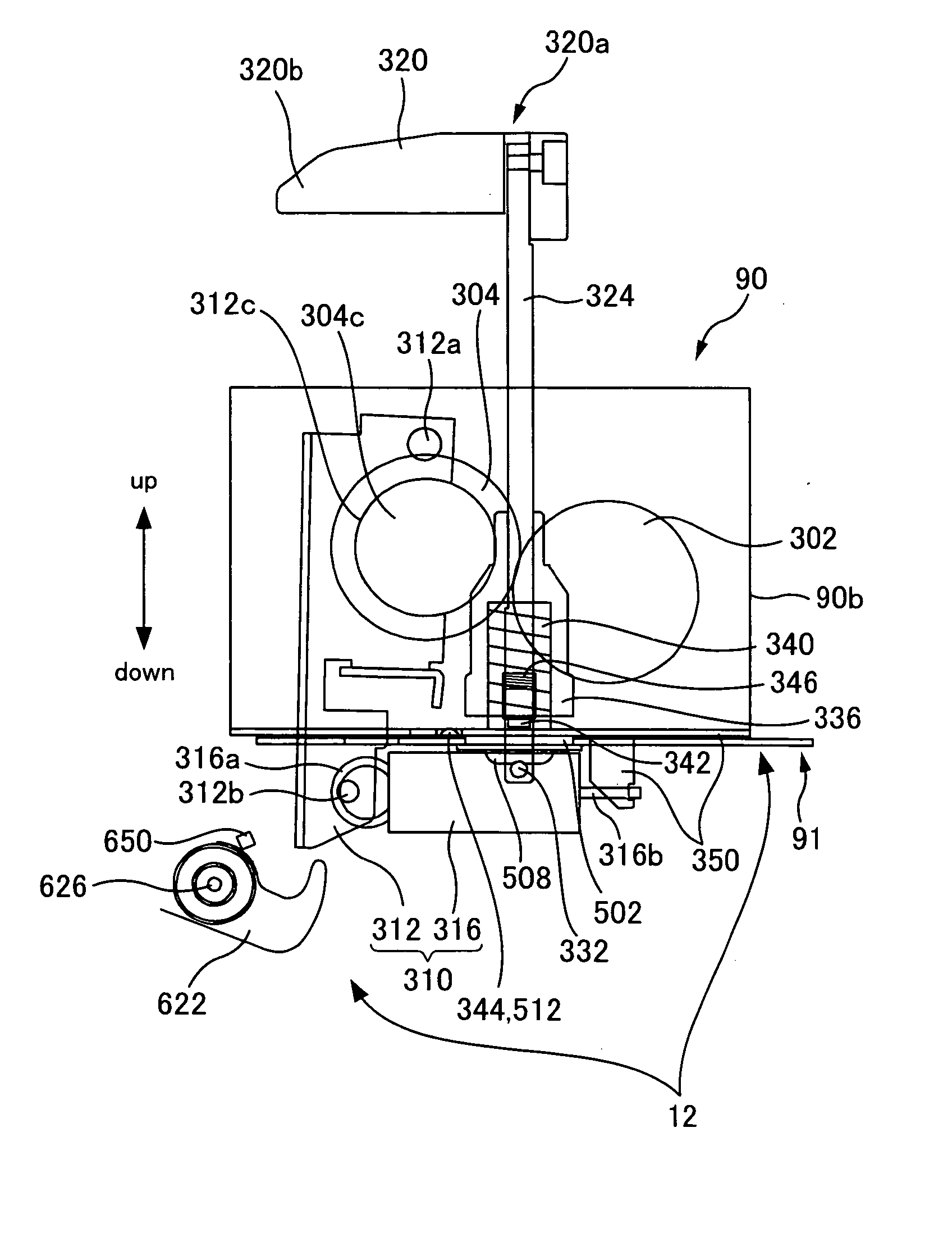
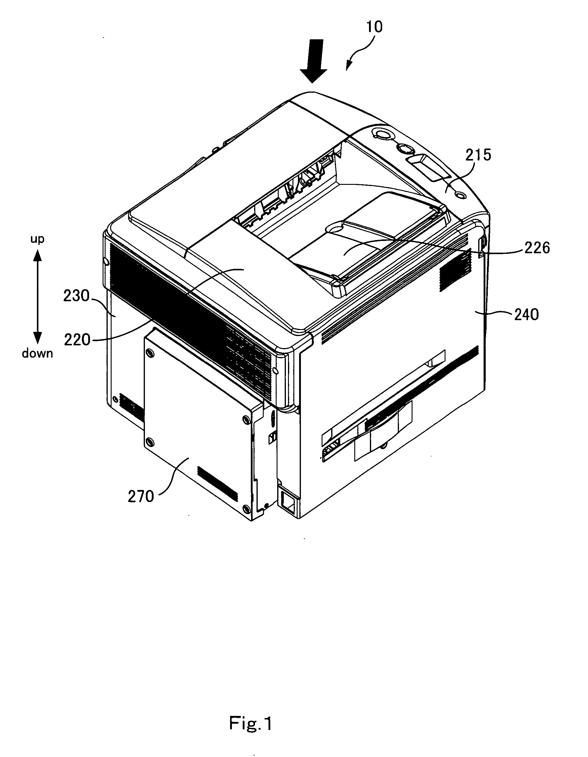
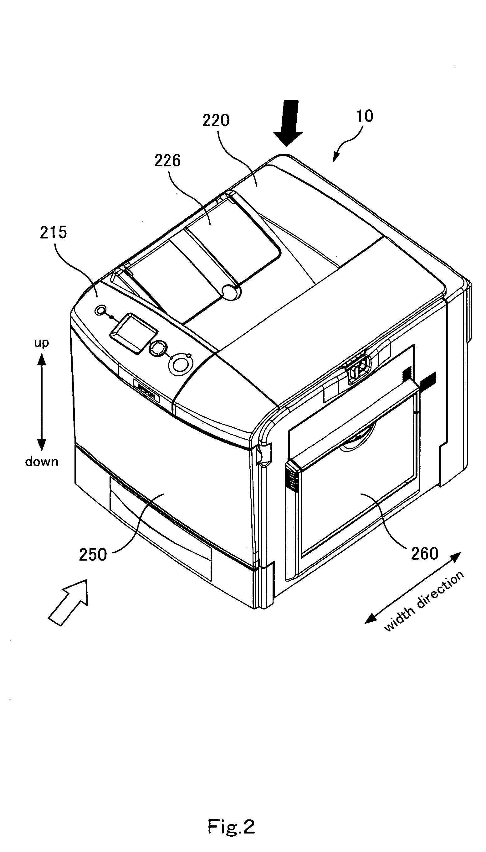
first embodiment
Other Embodiments of First Embodiment
[0400] In the foregoing, a fixing unit, a printer, etc. according to the present invention were described according to the foregoing first embodiment. However, the foregoing embodiment of the invention is for the purpose of facilitating understanding of the present invention and is not to be interpreted as limiting the present invention. The present invention can be altered and improved without departing from the gist thereof, and needless to say, the present invention includes its equivalents.
[0401] In the foregoing first embodiment, an intermediate-transferring-type full-color laser-beam printer was described as an example of an image forming apparatus. The present invention, however, is applicable to various types of image forming apparatuses such as full-color laser-beam printers of types other than the intermediate-transferring type, monochrome laser-beam printers, copying machines, and facsimile machines.
[0402] Further, the photoconductor...
second embodiment
Other Embodiments of Second Embodiment
[0512] In the foregoing, a fixing unit etc. according to the present invention was described according to the foregoing second embodiment. However, the foregoing embodiment of the invention is for the purpose of facilitating understanding of the present invention and is not to be interpreted as limiting the present invention. The present invention can be altered and improved without departing from the gist thereof, and needless to say, the present invention includes its equivalents.
[0513] In the foregoing second embodiment, an intermediate-transferring-type full-color laser-beam printer was described as an example of an image forming apparatus. The present invention, however, is applicable to various types of image forming apparatuses such as full-color laser-beam printers of types other than the intermediate-transferring type, monochrome laser-beam printers, copying machines, and facsimile machines.
[0514] Further, the photoconductor is not li...
PUM
 Abstract
Description
Claims
Application Information