Graphical user interface for tissue biopsy system

Active Publication Date: 2006-07-06
SENORX
View PDF88 Cites 71 Cited by
  • Summary
  • Abstract
  • Description
  • Claims
  • Application Information

AI Technical Summary

Benefits of technology

[0006] The invention is directed to a graphical user interface for a tissue biopsy system having a tissue cutting member adapted for cutting one or more tissue specimens from tissue at a target site within a patient.
[0007] In one embodiment, the graphical user interface includes at least a first GUI area and a second GUI area. The first GUI are

Problems solved by technology

Conventionally, when an electrosurgical biopsy instrument inserts into a patient's body, it's cutting end cannot be readily seen fr

Method used


Image

  • Graphical user interface for tissue biopsy system
  • Graphical user interface for tissue biopsy system
  • Graphical user interface for tissue biopsy system

Examples


Embodiment Construction

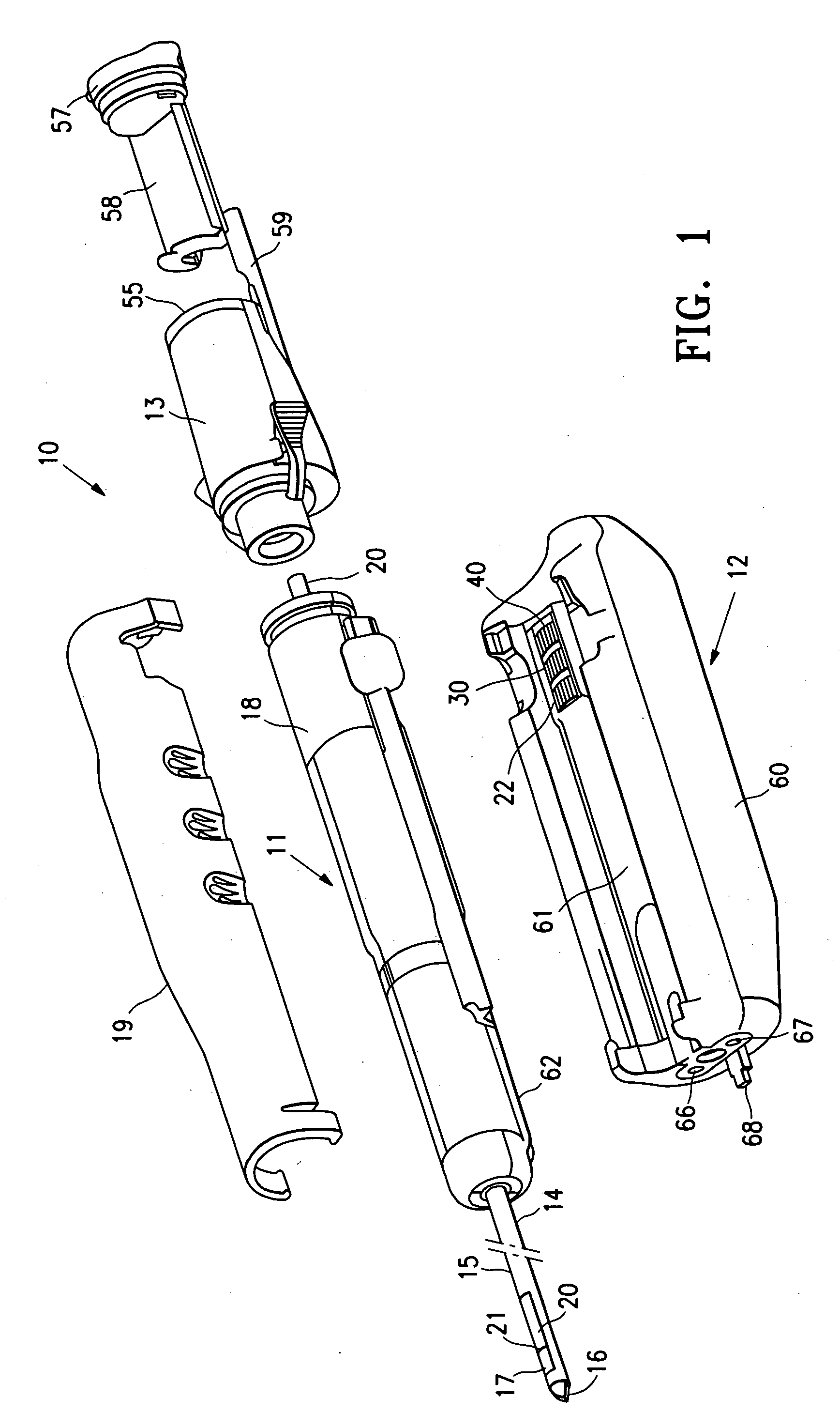
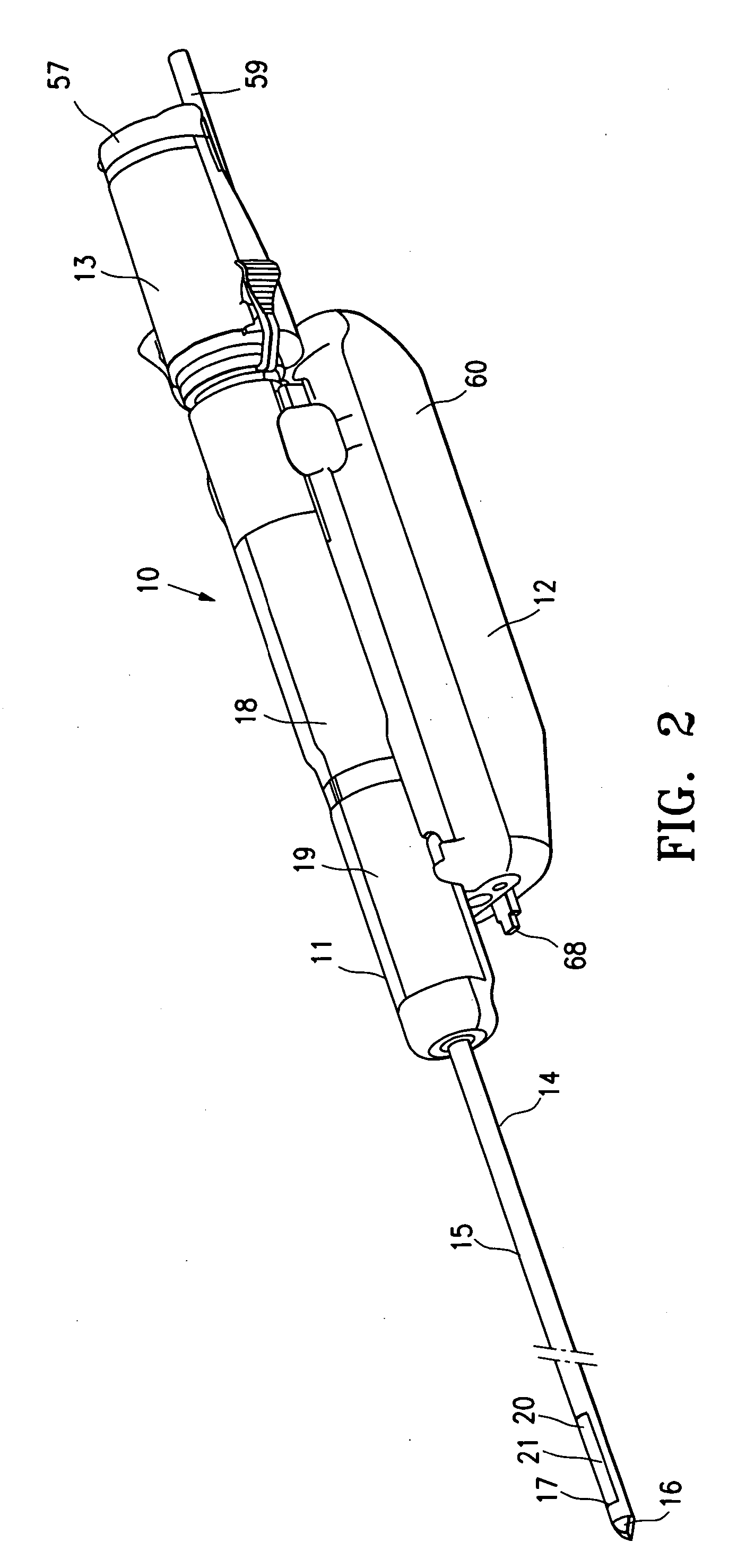
[0027]FIGS. 1-3 illustrate a biopsy system 10 embodying features of the invention which includes a disposable probe component 11, a driver component 12 and specimen collector 13.

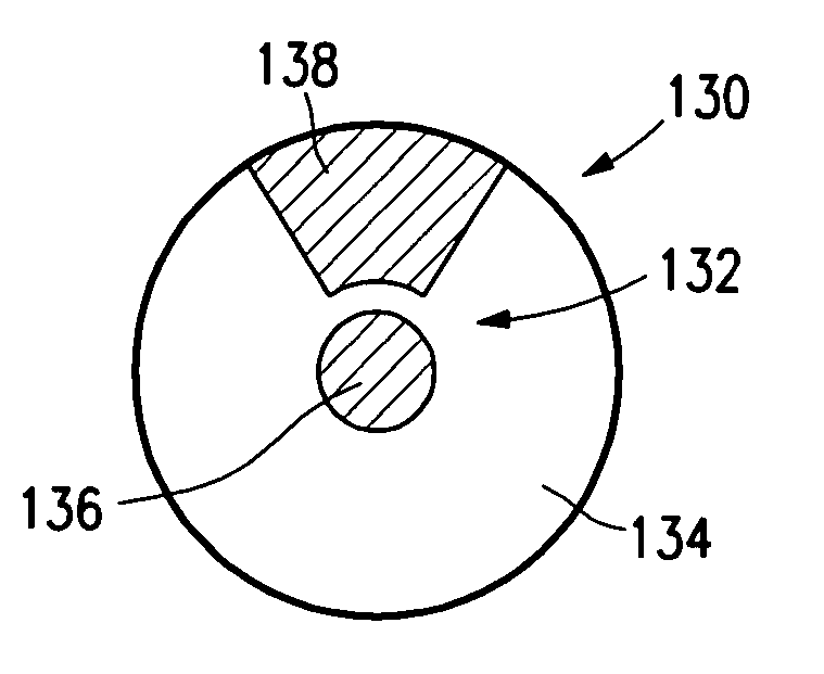
[0028] The probe component 11 generally includes an elongated distal shaft 14 having a tubular section or cannula 15 with a tissue penetrating tip 16 on the distal end thereof and an open, tissue receiving aperture 17. The probe component 11 also includes a probe housing 18 with a housing cover 19 which is configured to interfit with the driver component 12. A tissue cutter 20 is slidably disposed within the probe and has a distal cutting surface 21 which severs tissue which extends through the tissue receiving aperture 17.

[0029] Details of the probe component 11 are further shown in FIGS. 4A and 4B. The probe housing 18 has a mechanical system for rotating the housing and the tubular section 15 secured thereto to control the angular position of the tissue receiving aperture 17 and for moving the tissue cu...


PUM


Abstract

A graphical user interface is disclosed for a tissue biopsy system having a tissue cutting member adapted for cutting one or more tissue specimens from tissue at a target site within a patient. The graphical user interface includes a first GUI area representing a first region of the target site from which the tissue cutting member has separated one or more tissue specimens. The graphical user interface further includes a second GUI area, visually distinguishable from the first GUI area, representing a second region from which the tissue cutting member may separate one or more additional tissue specimens from tissue at the target site.

Description

RELATED APPLICATIONS [0001] This application is based on Provisional Application Ser. No. 60 / 631,338, filed on Nov. 29, 2004, and claims priority therefrom. The provisional application is incorporated by reference herein in its entirety.FIELD OF THE INVENTION [0002] The present invention relates generally to tissue removing devices such as biopsy devices. More specifically, it is directed to a graphical user interface (GUI) used in conjunction with the tissue removing devices. BACKGROUND OF THE INVENTION [0003] In diagnosing and treating certain medical conditions, such as potentially cancerous tumors, it is usually desirable to perform a biopsy, in which a specimen of the suspicious tissue is removed for pathological examination and analysis. In many instances, the suspicious tissue is located in a subcutaneous site, such as inside a human breast. To minimize surgical intrusion into the patient's body, it is desirable to be able to insert a small instrument into the patient's body ...

Claims


Application Information

Patent Timeline
IPC IPC(8): A61B10/00
CPCA61B19/20A61B19/5225A61B5/061A61B5/742A61B10/0275A61B10/0266A61B2019/564A61B90/10A61B2034/254A61B90/37G06T7/0012G06T2200/24A61B34/25A61B2034/107
Inventor DAW, DEREKLOUW, FRANK R.LUBOCK, PAULQUICK, RICHARD L.SHABAZ, MARTIN V.
Owner SENORX
Why Eureka
Try Eureka