Non-seeding biopsy device and method

a biopsy device and biopsy method technology, applied in the field of medical equipment and methods, to achieve the effect of reducing the risk of tumor cell seeding

Inactive Publication Date: 2008-09-16
PERCUTANEOUS SYST
View PDF43 Cites 22 Cited by
  • Summary
  • Abstract
  • Description
  • Claims
  • Application Information

AI Technical Summary

Benefits of technology

[0011]The present invention provides improved methods and systems for performing percutaneous tissue biopsy with reduced risk of tumor cell seeding. The method and system are useful for biopsy of virtually any solid tissue site where conventional needle biopsies may be performed, including breast biopsy, liver biopsy, renal biopsy, and the like.
[0013]The protective sleeve may be deployed over the outside of the cannula prior to introducing the catheter through tissue, for example being deployed over the cannula at the time of manufacture or by the physician immediately prior to use. More commonly, however, the protective sleeve will be provided in a furled configuration, where the sleeve is unfurled as the cannula is advanced through tissue, i.e. the cannula will pull on the sleeve and “tow” the sleeve into the tissue as the cannula is advanced. Typically, the furled sleeves will be contained in a separate canister or container, with an exemplary “egg” structure being shown in the drawings hereinafter. Providing the protective sleeve in a furled configuration is advantageous because it facilitates handling of the sleeve and minimizes contact of the sleeve with external body structures, thus limiting the risk of contaminating the sleeve before it is introduced to the tissue tract. Separating the sleeve from the cannula as the cannula is introduced also facilitates handling of the cannula since those portions not introduced into tissue will be directly manipulable, i.e., not encased in a slippery, loose-fitting sleeve.
[0015]Friction between the outer sleeve surface and tissue relative to that between the inner sleeve surface and cannula may be adjusted by texturing the various sliding surfaces. For example, by providing a smooth outer sleeve surface, friction with the tissue tract as the cannula is introduced will be reduced. In contrast, if both the inner sleeve surface and the outer cannula surface are smooth, the sleeve and cannula will tend to adhere. Thus, to increase the friction between the tissue and outer sleeve surface and reduce the friction between the outer cannula surface and the inner sleeve surface (which is the most desirable condition), it will generally be desirable to either texture the inner diameter of the protective sleeve or texture the outer diameter of the cannula (but not both). If both sides of the sleeve were textured, friction between the sleeve and the cannula would be increased (which is not desirable).
[0016]In some instances, it might be also be desirable to introduce “directional variation” in the friction presented by the sleeve. For example, it would be useful to modify an outer surface of the sleeve so that it experiences low friction as it penetrates tissue but presents higher friction if it is withdrawn from tissue. Such frictional characteristics would facilitate tissue penetration as well as helping immobilize the sleeve as the cannula is withdrawn. Such directional variation can be achieved, for example, by texturing the outer surface of the protective sleeve in a fish-scale or angled barb pattern to allow penetration of the sleeve and inhibit withdrawal of the sleeve through tissue. The texture on the outer surface of the sleeve will increase sliding friction in one direction compared to the other direction.
[0017]The protective sleeves will typically be formed from a polymer, with preferred polymers being listed above. The polymers will be extruded or otherwise formed as a tube with a wall thickness in the range from about 0.01 mm to 0.05 mm, preferably being in the range from 0.015 mm to 0.025 mm. The polymer or other sleeve material should, of course, be impermeable to cell passage so that any tumor cells trapped within the sleeve will not inadvertently escape through the sleeve wall.

Problems solved by technology

Any unintended adherence between the exterior of the cannula and the interior of the protective sleeves could interfere with such intended withdrawal.

Method used


Image

  • Non-seeding biopsy device and method
  • Non-seeding biopsy device and method
  • Non-seeding biopsy device and method

Examples


Embodiment Construction

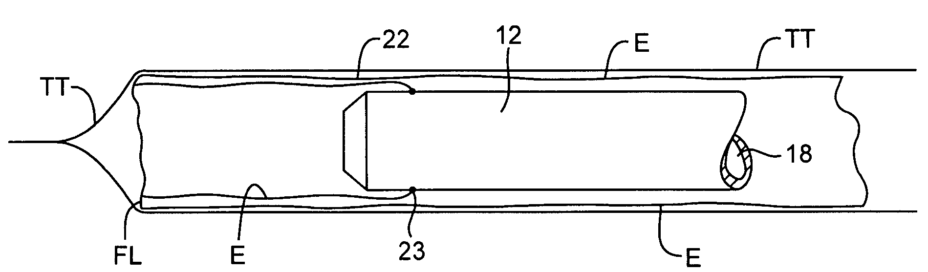
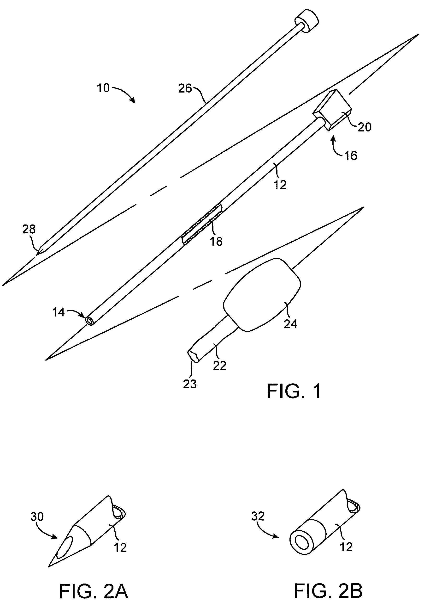
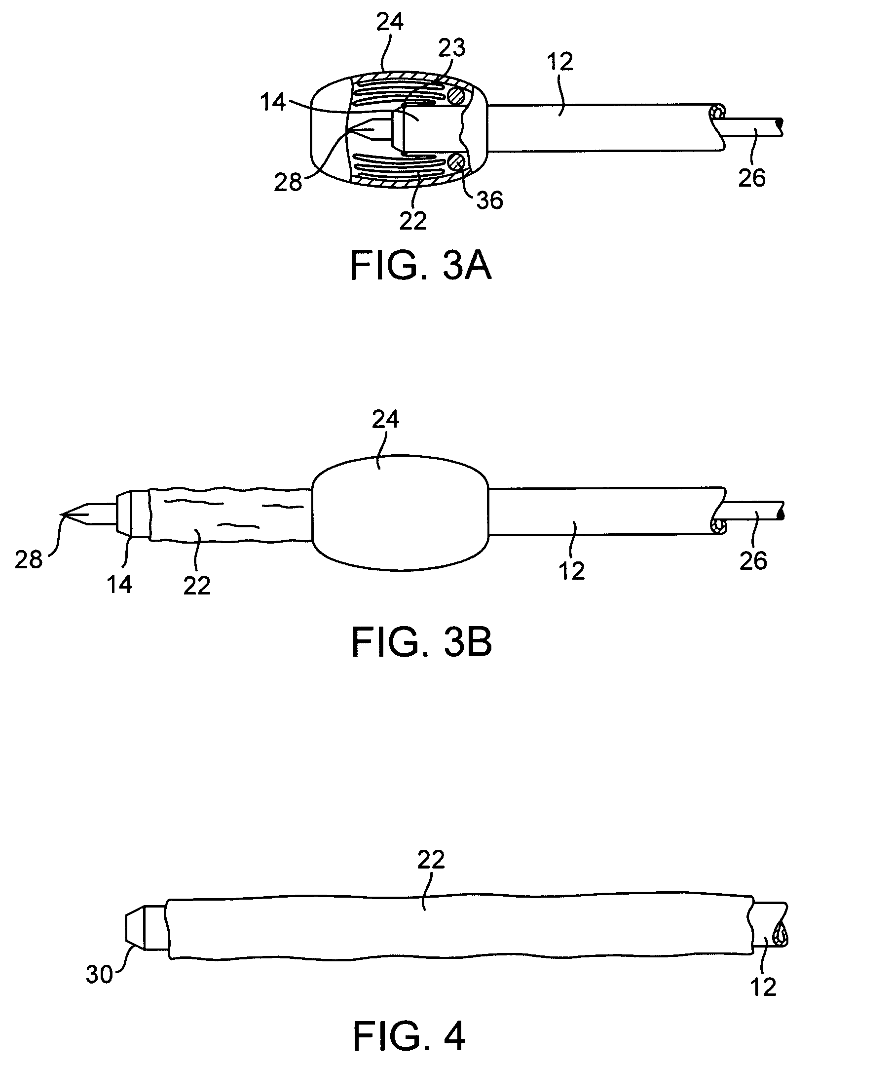
[0029]An exemplary system 10 constructed in accordance with the principles of the present invention includes a cannula 12 having a distal end 14, a proximal end 16, a central passage 18 therethrough, and a hub 20 at the proximal end. This will be described in more detail below. The lumen 18 permits introduction of a separate tissue biopsy instrument (not shown) for obtaining a tissue sample when the cannula is positioned adjacent a target site within solid tissue. Usually, a separate stylet 26 (described below) will also be provided to facilitate introduction of the cannula into tissue.

[0030]The system 10 further comprises a protective sleeve 22 which is preferably stowed within a canister 24 or other protective enclosure. The protective sleeve 22 is preferably furled, as best shown in FIG. 3A, and a leading edge 23 of the sleeve is attachable at or near the distal end 14 of the cannula 12. Usually, the leading edge 23 will be attached at or near the distal end of the cannula 12 at ...


PUM


Abstract

Tissue biopsy is performed through a central passage of a cannula covered with a protective sleeve. The protective sleeve is attached at one end to a location at or near a distal end of the cannula. After the biopsy procedure is completed, the cannula is withdrawn so that its exterior slides through the sleeve. In this way, the trailing edge of the sleeve is invaginated within the proximal portions of the itself to envelop the sleeve exterior and reduce the risk of inadvertent tumor cell seeding.

Description

BACKGROUND OF THE INVENTION[0001]1. Field of the Invention[0002]The present invention relates generally to medical apparatus and methods. More particularly, the present invention relates to a method and system for accessing a biopsy site in solid tissue while protecting the access tract from seeding with tumor cells.[0003]Percutaneous or “needle” biopsy of suspected malignancies is now in common use. Typically, an access sheath, such as a needle or cannula, is introduced through solid tissue to provide access to a target site in the tissue. A biopsy needle, biopsy gun, or similar device is then introduced through the needle or cannula to obtain a small tissue sample. The biopsy device is withdrawn through the needle or cannula, and the needle or cannula then withdrawn through the tissue tract to complete the procedure. The needle or cannula may also be incorporated as an integral portion of the biopsy device.[0004]While quite useful and generally successful, such “needle biopsy” pro...

Claims


Application Information

Patent Timeline
Patent Type & Authority Patents(United States)
IPC IPC(8): A61B10/00A61B17/32
CPCA61B10/0233A61B2017/3435A61B10/02A61B10/06
Inventor HUANG, ALEXANDERLAO, HENRYNEEDLEMAN, DAVID
Owner PERCUTANEOUS SYST
Why Eureka
Try Eureka