Materials handling vehicle having substantially all hydraulic components mounted on a main frame assembly

a technology of hydraulic components and material handling vehicles, which is applied in the direction of vehicle components, lifting devices, propulsion parts, etc., can solve the problems of inconvenient disassembly operation, contaminated lines/tubes, air in close proximity, etc., and achieves the reduction of the length of hydraulic tubes/lines required on the truck, simplified disassembly operation, and the effect of reducing the number of hydraulic tubes

Active Publication Date: 2006-07-13
CROWN EQUIP CORP
View PDF48 Cites 14 Cited by
  • Summary
  • Abstract
  • Description
  • Claims
  • Application Information

AI Technical Summary

Benefits of technology

[0004] In accordance with the present invention, a fork lift truck, such as a turret stockpicker truck, is provided comprising a power unit assembly detachably connected to a main frame assembly, wherein substantially all hydraulic components are mounted on the main frame assembly. Consequently, when the truck is separated, such as for shipping, no hydraulic tubes / lines extending between the power unit and main frame assemblies need be disconnected. Hence, the disassembly operation is simplified. Further, risk of moisture, dirt, air, etc. contaminating open hydraulic tubes / lines is reduced. Also, the length of hydraulic tubes / lines required on the truck is reduced since tubes / lines extending between the power unit and main frame assemblies are not required. This reduces costs as well as pressure drops within the hydraulic system.

Problems solved by technology

Such a disassembly operation is disadvantageous due to its complexity.
Also, disconnecting one or more hydraulic lines / tubes increases the risk that those lines / tubes may become contaminated with moisture, dirt, air, etc.
A further disadvantage to having the first hydraulic motor / pump assembly mounted on the power unit is that it is located in close proximity to many of the electronic and electrical components.
As a result, there is an increased risk that those electronic and electrical components may be contaminated with hydraulic fluid or dirt accumulated on the first hydraulic motor / pump assembly mounted to the power unit base.

Method used


Image

  • Materials handling vehicle having substantially all hydraulic components mounted on a main frame assembly
  • Materials handling vehicle having substantially all hydraulic components mounted on a main frame assembly
  • Materials handling vehicle having substantially all hydraulic components mounted on a main frame assembly

Examples


Embodiment Construction

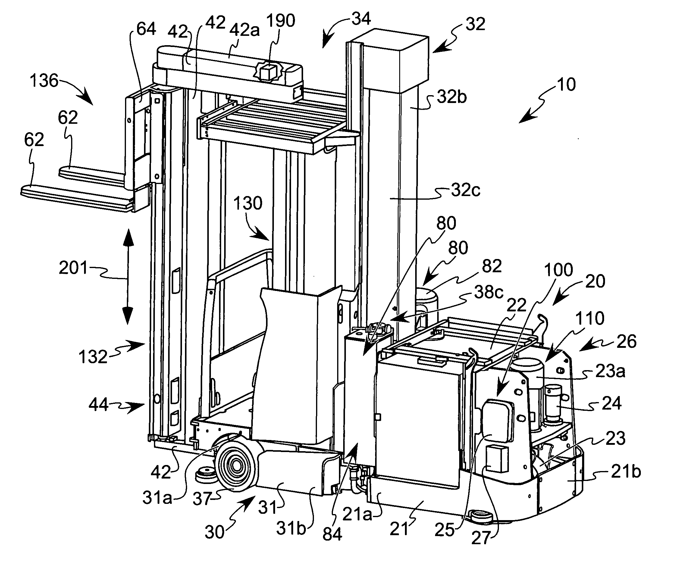
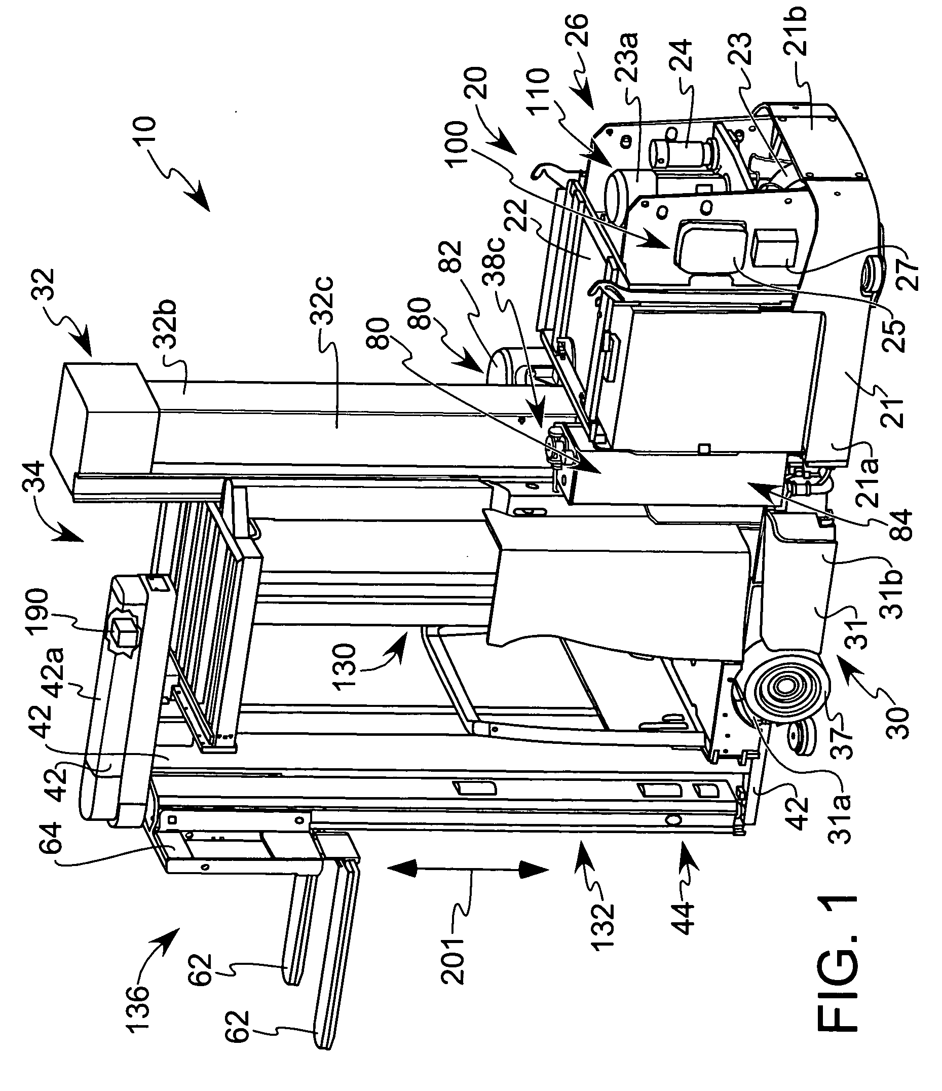
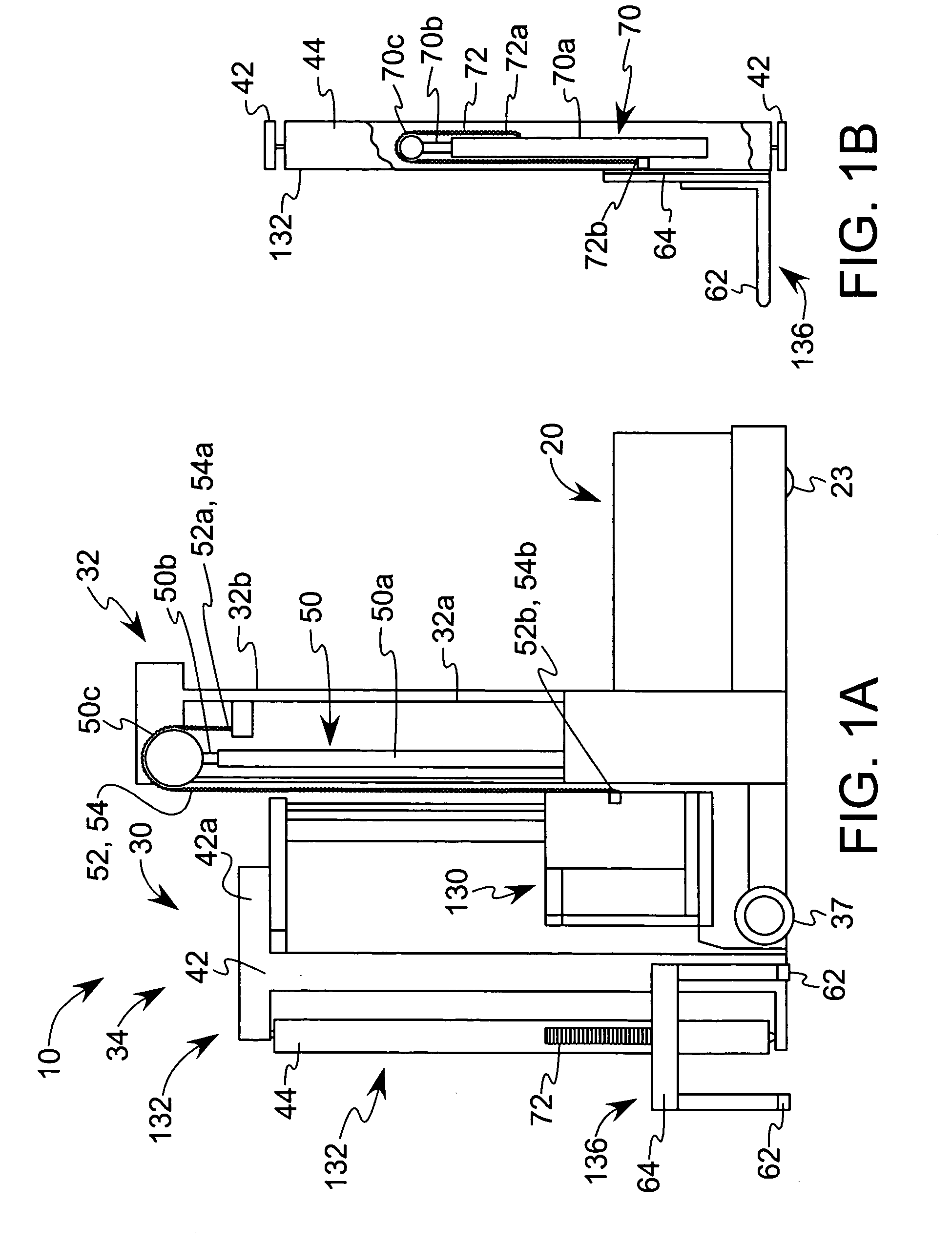
[0025] Referring now to the drawings, and particularly to FIGS. 1 and 2, which illustrate a materials handling truck or vehicle 10 constructed in accordance with the present invention. In the illustrated embodiment, the vehicle 10 comprises a turret stockpicker. The vehicle 10 includes a power unit assembly 20 and a main frame assembly 30, which assemblies 20 and 30 are releasably coupled together, as will be discussed more explicitly below. The power unit assembly 20 includes a power unit base 21 having front and rear portions 21a and 21b, respectively, a power source, such as a battery unit 22, positioned on the base 21, a steered wheel 23 rotatably coupled to the base rear portion 21b, a traction motor 23a for driving the wheel 23 and a traction motor control module 25 for controlling the operation of the traction motor 23a, i.e., its speed and direction, in response to operator generated commands, see FIGS. 1, 2 and 4. The main frame assembly 30 comprises a main frame base 31 ha...


PUM


Abstract

A lift truck is provided comprising: a power unit assembly comprising a power unit base, a wheel coupled to the base, and a system for driving the wheel; and a main frame assembly detachably connected to the power unit assembly. The main frame assembly comprises a main frame base, a mast assembly coupled to the main frame base, a carriage assembly coupled to the mast assembly, and hydraulic drive apparatus coupled to the mast assembly. Preferably, substantially the entirety of the hydraulic drive apparatus is provided on the main frame assembly such that the main frame assembly is detachable from the power unit assembly without requiring disconnecting hydraulic connections to the power unit assembly.

Description

TECHNICAL FIELD [0001] The present invention relates to a fork lift truck comprising a power unit assembly detachably connected to a main frame assembly, wherein substantially all hydraulic components are mounted on the main frame assembly. BACKGROUND OF THE INVENTION [0002] Fork lift trucks, such as turret stockpicker trucks, comprising a power unit assembly detachably connected to a main frame assembly are known in the prior art. In such a truck, the power unit assembly comprises a power unit base, at least one wheel coupled to the base and being driven by one or more traction motors, a battery for providing power to the traction motor(s), and a traction motor control module(s) for controlling the operation of the traction motor(s). A first hydraulic motor / pump assembly and at least one manifold valve block are also mounted on the power unit base. The main frame assembly comprises a main frame base, a mast assembly comprising a fixed first mast and a second mast movable relative t...

Claims


Application Information

Patent Timeline
Patent Type & Authority Applications(United States)
IPC IPC(8): B66F9/20
CPCB66F9/07545B66F9/07572B66F9/07568
Inventor KLUVER, LEROY M.KUCK, JAY L.
Owner CROWN EQUIP CORP
Why Eureka
Try Eureka