Al technical title is built by PatSnap Al team. It summarizes the technical point description of the patent document.
a coin and discriminator technology, applied in coin testing, paper-money testing devices, instruments, etc., can solve the problem of not being able to deal with bogus coins of similar metal content that are generally accurate, and achieve the effect of increasing the number of counterfeit coins that are rejected
Active Publication Date: 2006-07-13
SCAN COIN IND AB
View PDF31 Cites 16 Cited by
Summary
Abstract
Description
Claims
Application Information
AI Technical Summary
This helps you quickly interpret patents by identifying the three key elements:
Problems solved by technology
Method used
Benefits of technology
Problems solved by technology
The use of one or more recognition sets of parameters was proposed in GB 2135492A, each recognition set consisting of the highest and lowest values of the characteristic being measured, but this is not generally sufficiently accurate to deal with some bogus coins of a similar metal content.
Method used
Image
Click on the blue label to locate the original text in one second.
Reading with bidirectional positioning of images and text.
Examples
Embodiment Construction
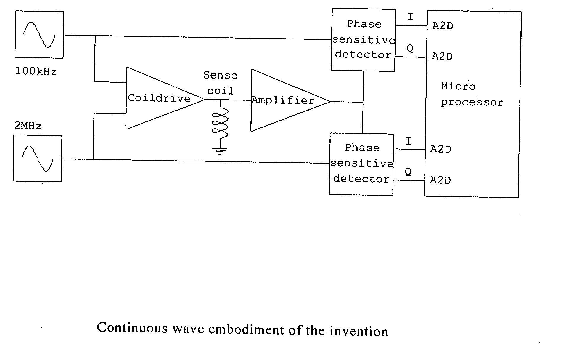
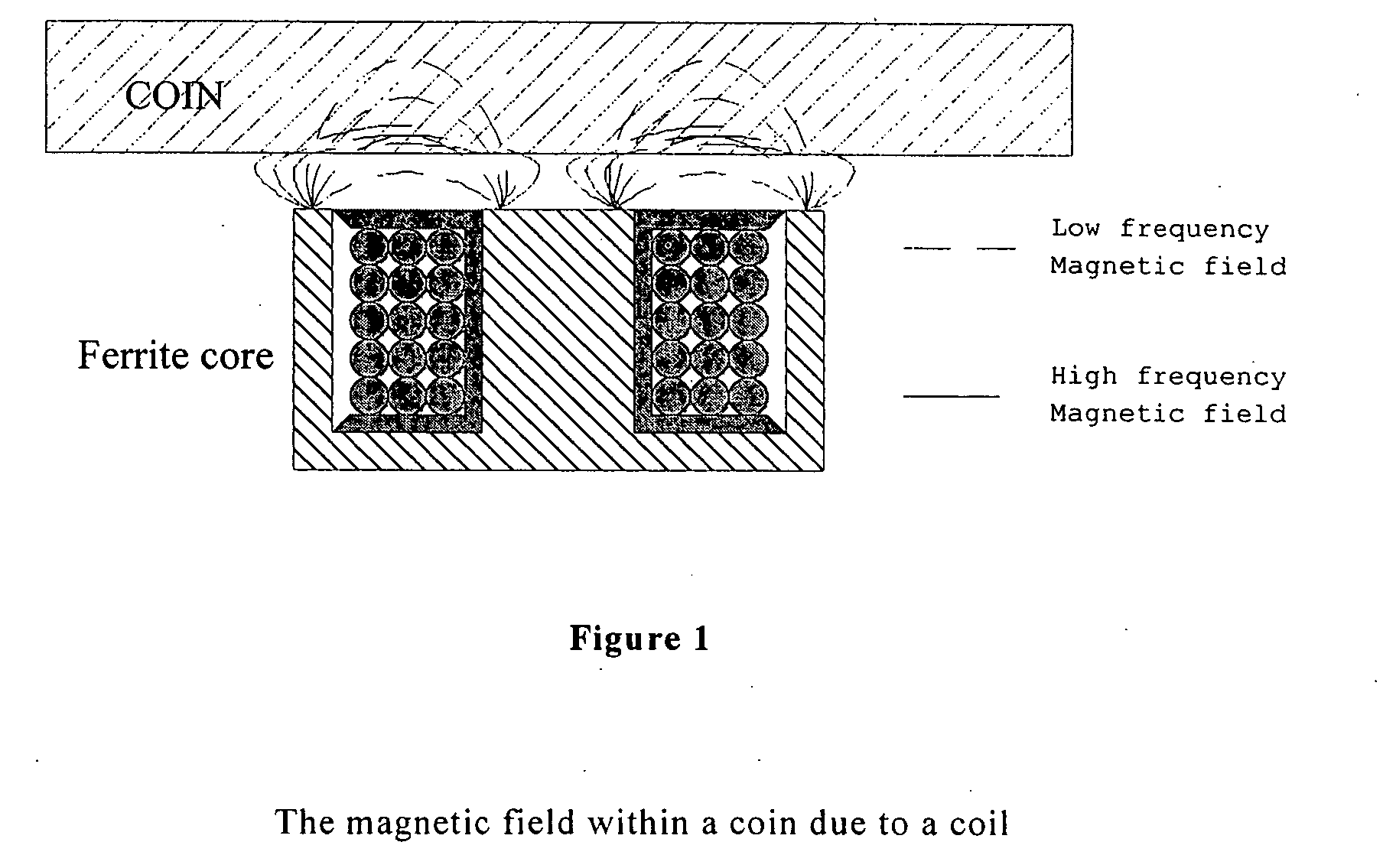
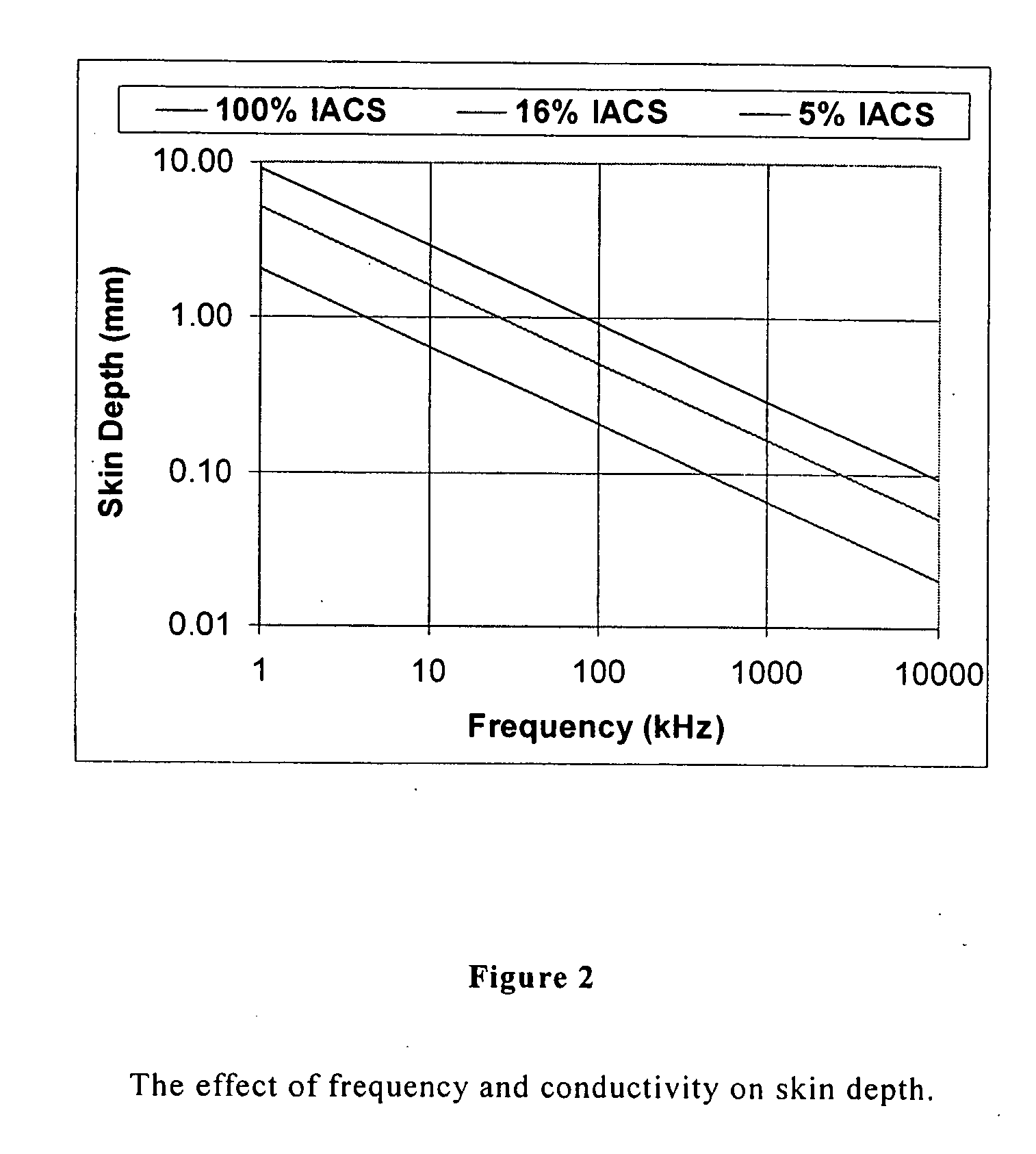
[0043] In one embodiment a single coil, such as the coil of FIG. 1, is driven at two frequencies. The low frequency is chosen to give a skin depth of just less than 1 mm, a depth that is less than the thickness of coins under test. The high frequency is chosen to give a skin depth of about 0.1 mm. The presence of a coin causes the apparent inductance and resistance of the coil to change. These changes are measured at both frequencies. From these changes the conductivity of the coin can be calculated. The high frequency change gives the surface conductivity and the low frequency ones the bulk conductivity.
[0044] If a large number of coins are measured and the conductivities are plotted against each other a distribution like the one shown in FIG. 3, is produced. The graph shows that coins with a high surface conductivity also have a high bulk conductivity and vice versa. This is to be expected, as the conductivity differences between the coins are caused by small variations in the ba...
PUM
Property
Measurement
Unit
frequencies
aaaaa
aaaaa
frequency
aaaaa
aaaaa
frequency
aaaaa
aaaaa
Abstract
A coin discriminator measures both the surface and average electrical conductivity of coins in order to distinguish genuine minted coins from fake or bogus coins such as cast coins which may be nominally of the same material as a minted coin. The conductivities are measured using a coil to induce eddy currents within the coin. The high frequency components of the eddy current are monitored to measure the surface conductivity. The low frequency components are measured to monitor the bulk or average conductivity. First and second signals are derived for each coin to provide a measurement set for that coin, the first signal being a measure of the conductivity of the surface skin of the coin, and the second signal being a measure of the conductivity of the body of the coin. The measurement set is then compared in some way with stored sets of reference signals obtained from a batch of minted coins in a calibration procedure, to determine the authenticity of the coin. In general, a distribution of sets of first and second signals obtained during the calibration procedure is stored, and then during subsequent testing of coins the measurement set is compared with the stored distribution, or with a mathematical expression which corresponds to that distribution. In a preferred arrangement the ratio of the first and second signals for the coin under test is compared with a reference ratio for first and second signals for a batch of minted coins. Continuous wave (CW) and pulse induction (PI) arrangements are described for obtaining the first and second signals. For improved characterisation of coins, eddy currents may be induced at a depth below the surface skin of the coin by use of an intermediate frequency of a continuous wave, or by a pulse of intermediate length in the PI method.
Description
CROSS-REFERENCE TO RELATED APPLICATIONS [0001] This application is a continuation of application Ser. No. 10 / 948,708, filed on Sep. 23, 2004; which application claims the benefit of provisional application no. 60 / 553,149, filed Mar. 15, 2004, and provisional application no. 60 / 553,220, filed Mar. 15, 2004, and which application also claims priority to British application no. GB0322354.2, filed Sep. 24, 2003, and British application no. GB0405616.4, filed Mar. 12, 2004. INCORPORATION BY REFERENCE [0002] The specification of U.S. application Ser. No. 10 / 948,708, filed on Sep. 23, 2004; provisional application no. 60 / 553,149, filed Mar. 15, 2004; provisional application no. 60 / 553,220, filed Mar. 15, 2004; British application no. GB0322354.2, filed Sep. 24, 2003; and British application no. GB0405616.4, filed Mar. 12, 2004 are incorporated herein in their entirety, by this reference. TECHNICAL FIELD [0003] The present invention relates to a coin discriminator and to a method of discrim...
Claims
Application Information
Patent Timeline
Application Date:The date an application was filed.
Publication Date:The date a patent or application was officially published.
First Publication Date:The earliest publication date of a patent with the same application number.
Issue Date:Publication date of the patent grant document.
PCT Entry Date:The Entry date of PCT National Phase.
Estimated Expiry Date:The statutory expiry date of a patent right according to the Patent Law, and it is the longest term of protection that the patent right can achieve without the termination of the patent right due to other reasons(Term extension factor has been taken into account ).
Invalid Date:Actual expiry date is based on effective date or publication date of legal transaction data of invalid patent.
Patent Type & Authority Applications(United States)