Torsionally de-coupled engine mount system

a technology of engine mounts and torsional separation, which is applied in the direction of machines/engines, vertical landing/take-off aircraft, efficient propulsion technologies, etc., can solve the problems of not being able to meet the requirements of a military presenting many unique challenges, and not being able to meet the requirements of a civilian-type tilt rotor aircraft. , to achieve the effect of reducing the load of the engine mounts, less complicated, and reduced

Active Publication Date: 2006-07-13
TEXTRON INNOVATIONS
View PDF12 Cites 5 Cited by
  • Summary
  • Abstract
  • Description
  • Claims
  • Application Information

AI Technical Summary

Benefits of technology

[0013] The torsionally de-coupled engine mount system of the present invention provides significant advantages. Loads in the engine mounts are significantly reduced. This allows the use of fewer parts that are less complicated and that weight less. This leads to commensurate cost and weight savings. For example, weight and cost of the system in the military-type tilt rotor aircraft application can be reduced by over 65%. The engine and pylon assembly can also be lighter, because with the present invention these components do have to be designed for high induced torque from the rotors. Dynamic analysis and tuning of the system is facilitated by simple structure and load paths. Dynamic and static problems are diminished by the significant reduction in system complexity. The system eliminates the need for highly loaded gimbal mounts and multiple link attachments.

Problems solved by technology

Often a design that is necessary in a military-type application is not commercially feasible in a civilian-type application.
In addition, civilian-type tilt rotor aircraft will have to comply with a considerable amount of governmental regulation.
Although tilt rotor aircraft provide many unique advantages, they also present many unique challenges.
One such challenge involves the mounting of the engines to the transmissions and other components in the aircraft.
Because the engines in tilt rotor aircraft are mounted to pylons and transmissions located at the ends of the wings in a manner that allows rotation relative to the wings, engine mounting techniques used in conventional helicopters and propeller driven aircraft are not adequate.
Although these changes in the engine mounting system solved the problems associated with the engines being cantilevered from the prop rotor gear boxes, they introduced other problems.
Thus, the introduction of multiple rigid links coupled near the aft end of the engine created torsional redundancy in the engine.
In other words, these prior-art techniques unnecessarily allowed a portion of the rotor torque to be induced into the engine-pylon loop.
The foregoing represents great strides in the design and manufacture of tilt rotor aircraft; however, many challenges remain, particularly in the area of engine mounting systems.

Method used


Image

  • Torsionally de-coupled engine mount system
  • Torsionally de-coupled engine mount system
  • Torsionally de-coupled engine mount system

Examples


Embodiment Construction

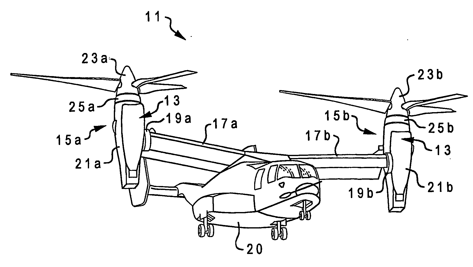
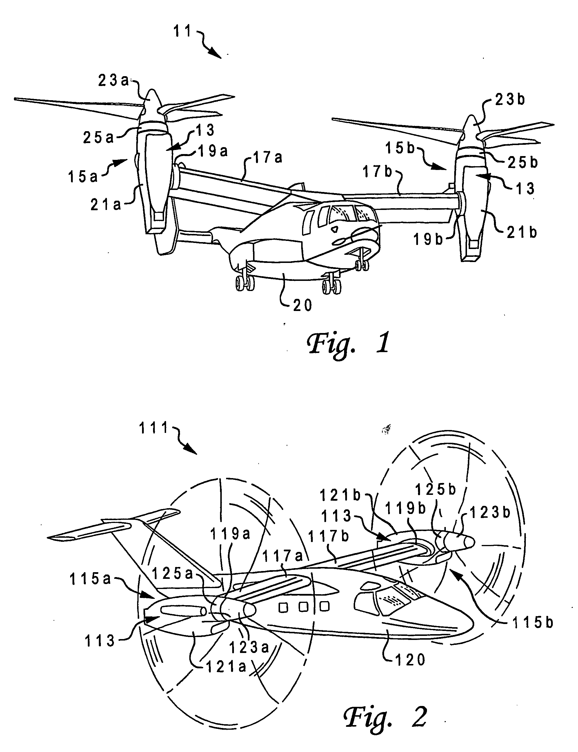
[0031] Referring to FIG. 1 in the drawings, a military-type tilt rotor aircraft 11 having a torsionally de-coupled engine mount system 13 according to the present invention is illustrated. Tilt rotor assemblies 15a and 15b are carried by wing members 17a and 17b, and are disposed at end portions 19a and 19b of wing members 17a and 17b, respectively. Wing members 17a and 17b are coupled to a fuselage 20. Tilt rotor assemblies 15a and 15b include nacelles 21a and 21b, which house the engines, transmissions, and prop rotor gear boxes that drive rotors 23a and 23b disposed on forward ends 25a and 25b of nacelles 21a and 21b.

[0032] Tilt rotor assemblies 15a and 15b move or rotate relative to wing members 17a and 17b between a helicopter mode in which tilt rotor assemblies 15a and 15b are tilted upward, such that tilt rotor aircraft 11 can take off, hover, fly, and land like a conventional helicopter; and an airplane mode in which tilt rotor assemblies 15a and 15b are tilted forward, suc...


PUM


Abstract

A torsionally de-coupled engine mount system (13) for use in tilt rotor aircraft (11) applications is disclosed, in which an engine is mounted at its forward end to a prop rotor gear box by means of a forward mount (303) that is a simple adapter fitting, and at its aft end to a pylon assembly by an aft mount (305) that is a simple bi-pod fitting. The forward mount (303) counteracts forces and moments in six degrees of freedom, but the aft mount (305) only counteracts lateral and vertical loads. The contribution from the engine to the overall dynamic response of the aircraft is tuned by selectively tailoring the size, shape, weight, and material of the forward mount (303). The engine mount system torsionally de-couples the engines from the prop rotors, thereby preventing rotor torque from being induced into the engines. In addition, the contribution from the engines to the overall dynamic response of the aircraft can be tuned by selectively tailoring the size, shape, weight, and material of the forward mounts between the engines and the transmissions.

Description

TECHNICAL FIELD [0001] The present invention relates to systems for mounting engines in aircraft. In particular, the present invention relates to systems for mounting engines in tilt rotor aircraft. DESCRIPTION OF THE PRIOR ART [0002] Tilt rotor aircraft are unique in that they have tilt rotor assemblies that operate between a helicopter mode in which the tilt rotor assemblies are rotated upward allowing the tilt rotor aircraft to take off, hover, fly, and land like a conventional helicopter; and an airplane mode, in which the tilt rotor assemblies are tilted forward allowing the tilt rotor aircraft to fly like a conventional fixed-wing propeller driven aircraft. The first tilt rotor aircraft were designed strictly for military or research purposes, but now plans are being made to manufacture civilian-type tilt rotor aircraft. [0003] Aside from the vast differences between tilt rotor aircraft and conventional helicopters and propeller driven aircraft, there are significant differenc...

Claims


Application Information

Patent Timeline
Patent Type & Authority Applications(United States)
IPC IPC(8): B64C27/22B64C27/14B64C27/28B64C29/00B64D27/26B64D35/00B64F5/00F02C7/20F02C7/36
CPCB64C27/14B64C27/28B64C29/0033B64D27/12B64D27/26B64D2027/266B64F5/0045F02C7/20F02C7/36Y02T50/44Y02T50/671B64F5/60Y02T50/40Y02T50/60
Inventor HOWARD, JOHN V.MILDENSTEIN, STEPHEN E.
Owner TEXTRON INNOVATIONS
Why Eureka
Try Eureka