Method of controlling battery current limiting

a current limitation and battery technology, applied in battery overheating protection, safety/protection circuits, transportation and packaging, etc., can solve the problems of easy degradation of battery characteristics, difficult repeated discharging to complete battery discharge or charging to a fully charged state, and increase in the error state of charge over time, so as to reduce battery degradation

Inactive Publication Date: 2006-07-13
SANYO ELECTRIC CO LTD
View PDF3 Cites 99 Cited by
  • Summary
  • Abstract
  • Description
  • Claims
  • Application Information

AI Technical Summary

Benefits of technology

[0007] The present invention was developed to solve the types of problems described above. Thus it is a primary object of the present invention to provide a method of controlling battery current limiting that can reduce battery degradation by limiting charging and discharging currents within acceptable ranges, even when the state of charge of the battery is not accurately determined from charging and discharging currents and voltages.

Problems solved by technology

The first state of charge computed from the integral of current can accurately detect variation in the state of charge, but since error accumulates, error in the state of charge increases over time.
However, discharging to complete battery discharge or charging to a fully charged state are difficult to repeat frequently in practice.
This is because battery characteristics become easily deteriorated as the state of charge approaches complete discharge and full charge, and characteristics are markedly degraded by over-charge and over-discharge.
In addition, the battery cannot be further discharged in the fully discharged condition, and time is required to reach full charge.
These factors also make repetition of complete discharge and charging to full charge difficult.

Method used


Image

  • Method of controlling battery current limiting
  • Method of controlling battery current limiting
  • Method of controlling battery current limiting

Examples


Embodiment Construction

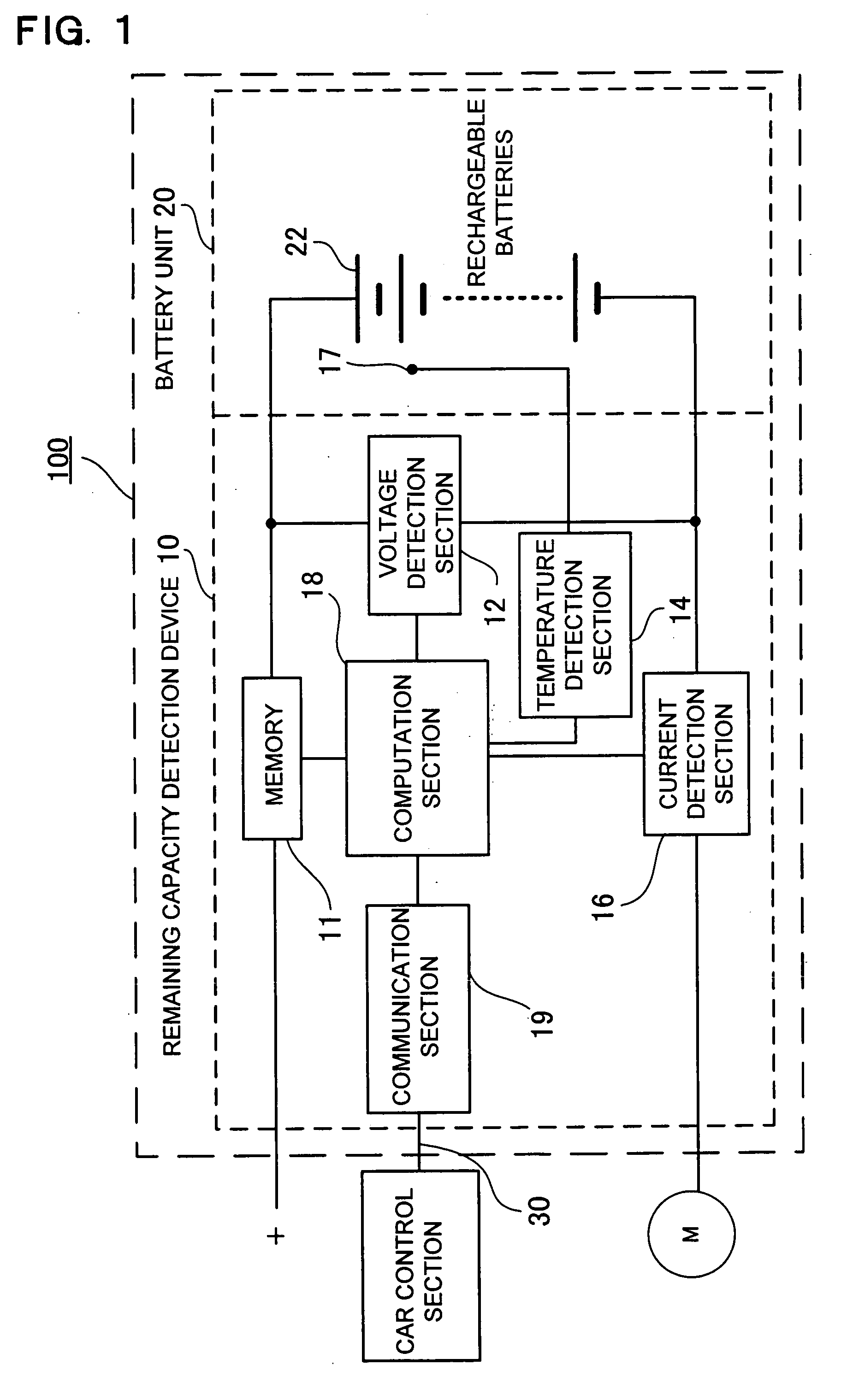
[0020] Turning to FIG. 1, a block diagram showing the structure of one example of a power source apparatus used in an embodiment related to the method of controlling battery current limiting of the present invention is illustrated. The power source apparatus 100 of this figure is provided with a battery unit 20, which includes rechargeable batteries 22, and a remaining capacity detection device 10. The remaining capacity detection device 10 is provided with a voltage detection section 12 to detect battery voltage; a temperature detection section 14 to detect battery temperature; a current detection section 16 to detect battery current flow; a computation section 18 to operate on signals input from the voltage detection section 12, the temperature detection section 14, and the current detection section 16 and to determine the remaining capacity or state of charge of the battery and battery unit 20 maximum current limit values from the state of charge and battery temperature; and a co...


PUM


Abstract

The method of controlling battery current limiting controls maximum charging and discharging current values according to the state of charge of the battery. The method of controlling current limiting integrates battery charging and discharging current to compute a first state of charge, determines first charging and discharging current limit value candidates from that first state of charge, computes a second state of charge based on battery voltage, and determines second charging and discharging current limit value candidates from that second state of charge. Further, the method takes the smaller of the first and second charging and discharging current limit value candidates as the charging and discharging current limit values for charging and discharging the battery.

Description

BACKGROUND OF THE INVENTION [0001] This invention relates to a method of limiting maximum charging and discharging current values based on the state of charge or remaining capacity of the battery, and for example, relates to a method of controlling battery current limiting to limit maximum current through batteries included in a power source apparatus for powering the driving motor a car. [0002] Batteries have the property that their electrical characteristics degrade if discharged at high current when their state of charge is low, or if charged with high current when their state of charge is high. For this reason it is important to limit maximum charging and discharging currents for batteries in a power source apparatus that, for example, powers a car driving motor. If maximum current is not limited, rapid car acceleration when the state of charge of the battery is low can cause battery voltage to suddenly drop due to high discharge current. In addition, sudden braking when the sta...

Claims


Application Information

Patent Timeline
Patent Type & Authority Applications(United States)
IPC IPC(8): H02J7/00
CPCH02J7/0029H02J7/0063H02J7/0072H02J2007/0067H02J7/00716H02J7/00302H02J7/00306H02J7/007182H02J7/007194H02J7/00309
Inventor MATSUMOTO, KENSHITAMEZANE, SHIGETO
Owner SANYO ELECTRIC CO LTD
Why Eureka
Try Eureka