System and method for radiating RF waveforms using discontinues associated with a utility transmission line

a technology of discontinuous waveforms and transmission lines, which is applied in the field of system and method for radiating discontinuous waveforms associated with utility transmission lines, can solve the problems of inability to determine the location of targets that generate noise, inability to detect moving targets in time, and inability to find cracks or holes

Inactive Publication Date: 2006-07-13
TDC ACQUISITION HLDG
View PDF16 Cites 88 Cited by
  • Summary
  • Abstract
  • Description
  • Claims
  • Application Information

AI Technical Summary

Benefits of technology

[0007] Briefly, according to the present invention, a system and method for radiating radio frequency (RF) waveforms generates an RF waveform resulting in emissions from one or more emission points. The generated RF waveform, which can be coupled to the utility transmission line using a Balun, a transformer, or a coupler, comprise any suitable RF waveform, including a UWB waveform such as a Gaussian pulse waveform, a pulse doublet waveform, a pulse triplet waveform, a pulse quadlet waveform, or a burst of cycles waveform. One or more RF reflections of the emitted RF waveform are received at one or more reception points. At least one of the one or more emission points and the one or more reception points comprises an impedance discontinuity coupled to a utility transmission line that provides a public

Problems solved by technology

The disadvantage of acoustical systems lies in the fact that without an array of directional listening devices, it is almost impossible to determine the location of the targets that generate noise.
Furthermore, moving targets may not make enough noise to be detected.
The drawbacks of this solution are that it takes time to find a crack or drill a hole and it is noisy to do so.
Thus, in a hostage

Method used


Image

  • System and method for radiating RF waveforms using discontinues associated with a utility transmission line
  • System and method for radiating RF waveforms using discontinues associated with a utility transmission line
  • System and method for radiating RF waveforms using discontinues associated with a utility transmission line

Examples


Embodiment Construction

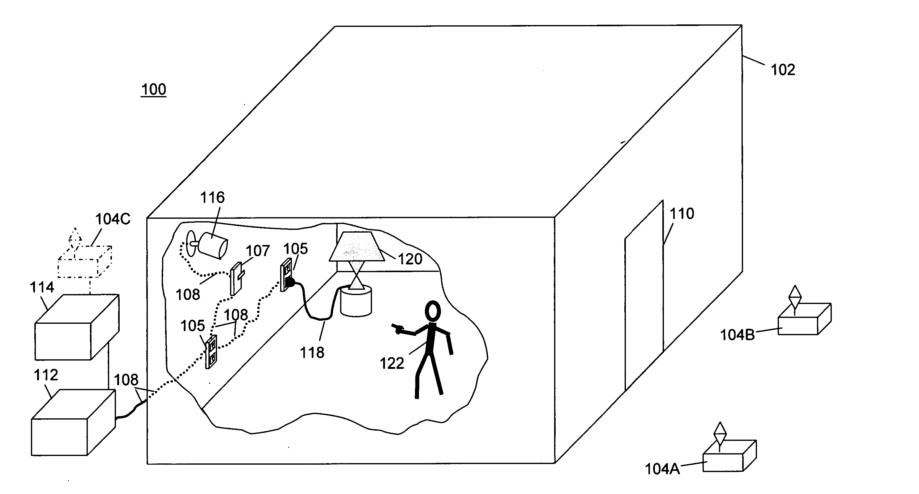
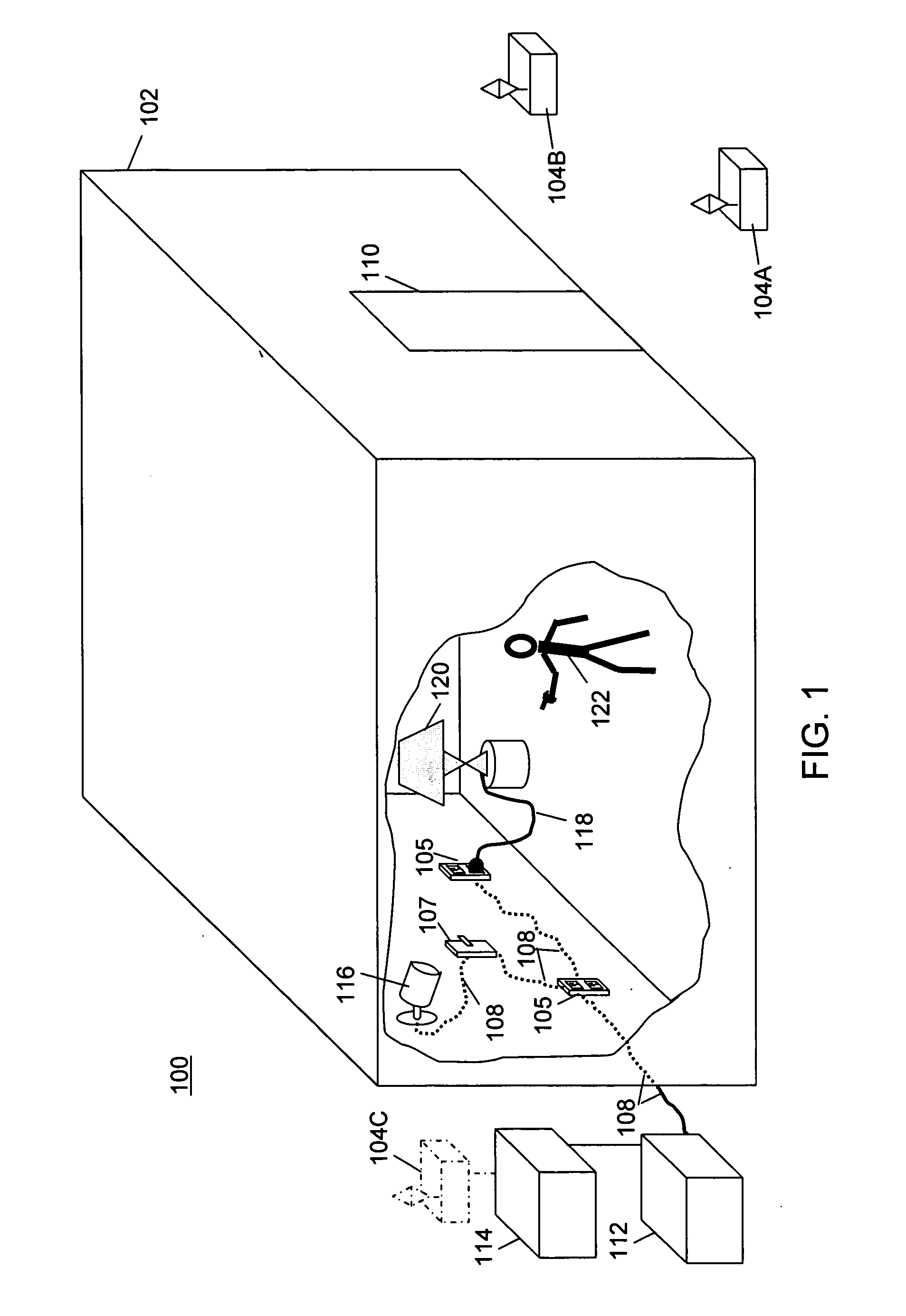
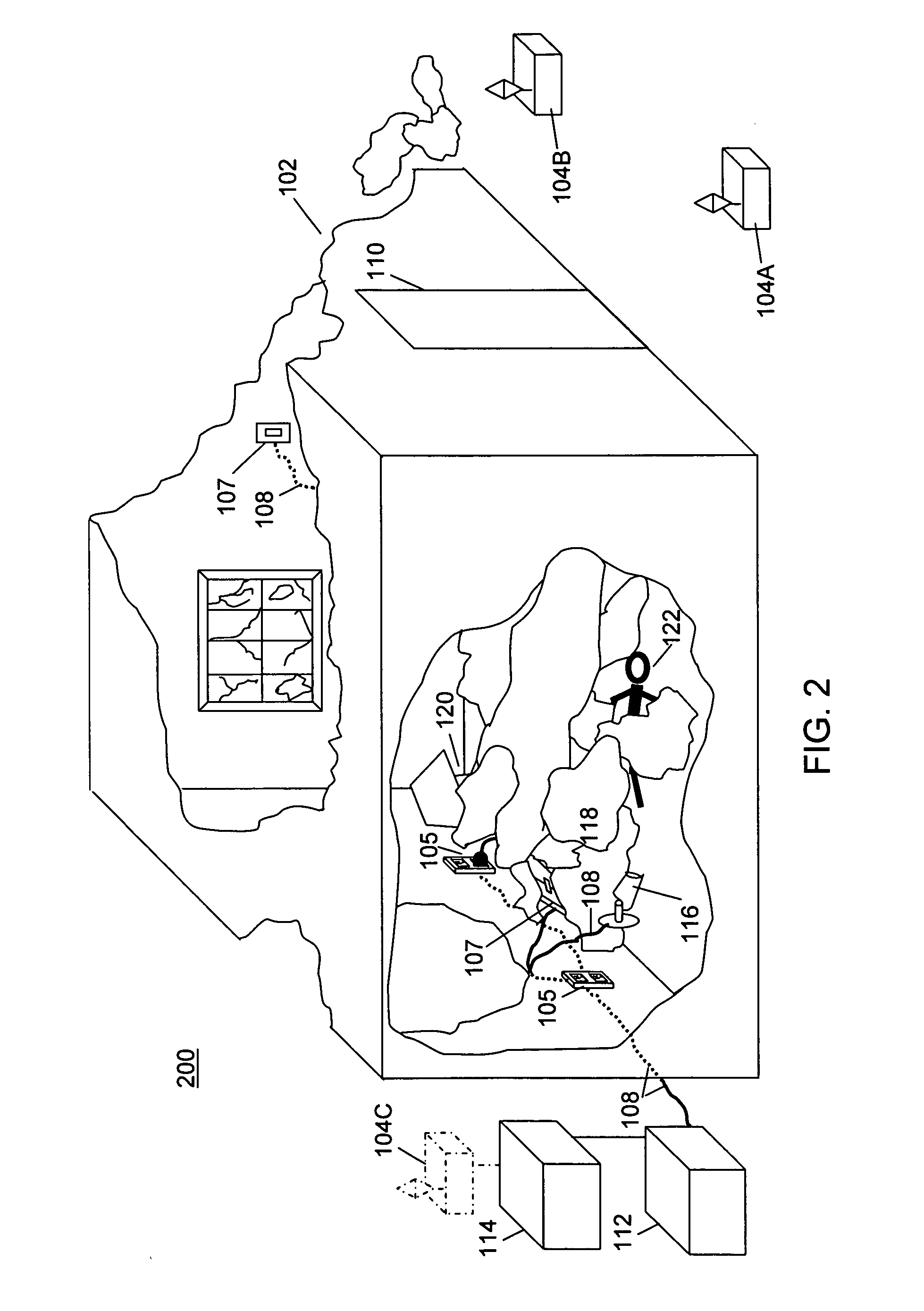
[0029] The present invention processes emitted RF waveforms, such as UWB waveforms, and their received reflections for radar applications, where the emission, reception or both are via an impedance discontinuity, which is coupled to a transmission line that provides a public or private utility service. Such transmission line could be in service to provide electric utility, telephone, cable, LAN, audio / video, etc. The radar applications used with the present invention include profiling waveform reflections in an environment, detecting presence or location of objects, tracking motion of targets, detecting intrusion, etc., as described fully below.

[0030] Because the exemplary embodiment of the invention uses UWB waveform and impulse technology, the following provides an overview of relevant aspects of such communications theory to assist the reader with full understanding of the present invention. It should be noted that while, the exemplary embodiment is described based on impulse ra...


PUM


Abstract

A method for processing radio frequency reflections is provided. The method applies an RF waveform to a transmission line that is a conductor used for providing a utility service. The method uses a RF waveform generator to transmit UltraWideband (UWB) RF waveforms through the conductors of a building. The RF waveforms are emitted at emission points that can be impedance discontinuities along the transmission line or impulse radios. The emitted RF waveforms reflect off of objects in the building and are received at reception points that can be impedance discontinuities or impulse radios. These reflections are processed to determine movement of objects within or near the building. Based on the reflections of the RF waveforms, the position of the objects within or near the building can be determined.

Description

BACKGROUND OF THE INVENTION [0001] Radar is a device or system consisting of an emitter that emits waves (RF, acoustic, etc.) that reflect off objects and a receiver that receives the reflections of the emitted waves for processing to detect, track or locate the objects. Various radar systems are known for detecting presence of objects, persons, things, etc. In one application, a security radar system detects unauthorized intrusions into a protected area. Such security systems operate based on activation of an intrusion sensing device, such as an acoustic motion detector, to generate an alert or alarm when an unauthorized intrusion is detected, for example, by placing a call to a remote police station. Systems that detect presence of objects have also been used to provide information related to the number and position of objects, things or persons within enclosed structures. Such systems have also been used to find survivors within the rubble of collapsed buildings. [0002] The so-ca...

Claims


Application Information

Patent Timeline
IPC IPC(8): G01S13/62
CPCG01S7/414G01S13/003G01S13/04G01S13/888G08B13/1636G08B21/22
Inventor FULLERTON, LARRY W.ROBERTS, MARK D.
Owner TDC ACQUISITION HLDG
Why Eureka
Try Eureka