Information recording device and information recording method

a technology of information recording and information recording, which is applied in the field of optically recording information, can solve the problems of difficult to obtain an accurate emitting waveform, inability to form satisfactorily marks, and sometimes worse recording characteristics, and achieve the effect of accurate formation of pits on optical discs

Inactive Publication Date: 2006-07-13
PIONEER CORP
View PDF9 Cites 6 Cited by
  • Summary
  • Abstract
  • Description
  • Claims
  • Application Information

AI Technical Summary

Benefits of technology

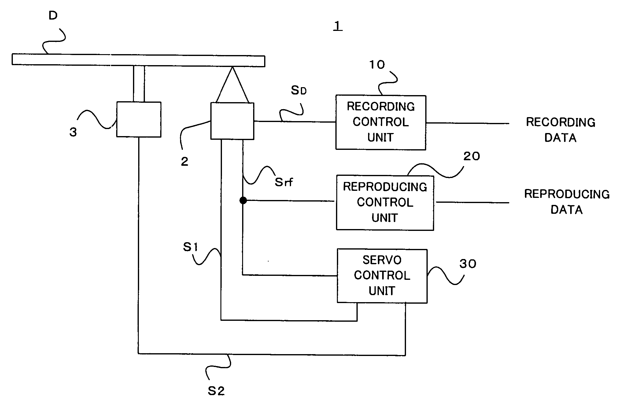
[0007] The present invention has been achieved in order to solve the above problems. It is an object of this invention to provide an information recording method and an apparatus thereof which are hardly affected by a characteristic of the recording apparatus even during a time of high-speed recording, and which can accurately form pits on an optical disc by ensuring enough time for heating and cooling.

Problems solved by technology

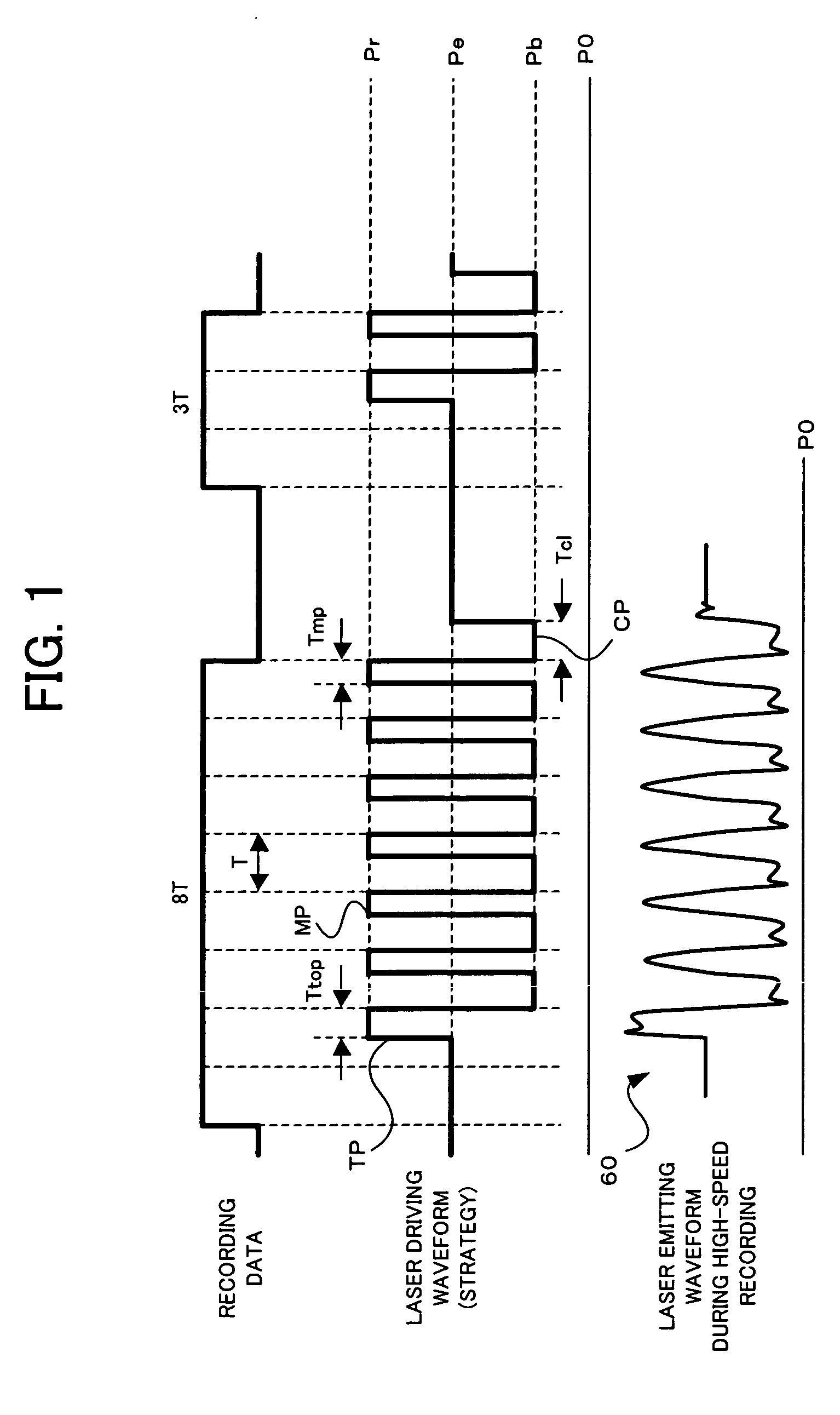
Therefore, if the base clock becomes higher speed in the high-speed recording and the time of 1 T becomes shorter, it becomes difficult to obtain an accurate emitting waveform because the rounding portion of the multi-pulse waveform becomes larger by a transient response.
Also, since heating by the laser beam and cooling cannot be executed longer than a 1 T time period in the multi-pulse period, the mark cannot be formed satisfactorily dependently on the characteristic of the optical disc, and the recording characteristic sometimes becomes worse, like the decrease of a signal modulating degree.

Method used


Image

  • Information recording device and information recording method
  • Information recording device and information recording method
  • Information recording device and information recording method

Examples


1st modification

(1st Modification)

[0069] Next, the strategy according to the first modification will be explained. FIGS. 9A to 9C show the laser driving waveform of each recording mark length according to the first modification. The first modification is different from the basic embodiment in that the top pulse TP is formed by the two pulses for the recording mark belonging to the group G3. In the first modification, the laser driving waveforms of the recording mark lengths belonging to the groups G1 and G2 are identical to those of the basic embodiment shown in FIGS. 8A to 8C.

[0070] As to the recording marks belonging to the group G3, i.e., 5 T, 8 T, 11 T and 14 T, it is determined whether the top pulse TP is one, like the basic embodiment shown in FIGS. 8A to 8C, or two, like the first modification, dependently on the recording characteristic of the optical disc subjected to the recording. Namely, the first modification is effective when 5 T mark can not be preferably formed by only a pair of th...


PUM

PropertyMeasurementUnit
timeaaaaaaaaaa
lengthaaaaaaaaaa
widthaaaaaaaaaa

Abstract

In a recording strategy suitable for high-speed recording, a laser driving signal includes a top pulse having a pulse width corresponding to a recording mark length and multi-pulses having a period 3-times larger than a base clock period of a recording mark. The top pulse is has the first identical-shape top pulses when the recording mark length is 3 nT (“n” is a natural number), the second identical-shape top pulses when the recording mark length is (3 n+1)T, and the third identical-shape top pulses when the recording mark length is (3n+2)T.

Description

TECHNICAL FIELD [0001] This invention relates to a method of optically recording information on an information recording medium. BACKGROUND TECHNIQUE [0002] Onto a recordable or rewritable optical disc such as a DVD-R (DVD-Recordable) or a DVD-RW (DVD-Rerecordable), information is recorded thereon by irradiating a laser beam on its recording surface. At the areas on the recording surface of the optical disc where the laser beam is irradiated, the property of the optical recording medium forming the optical disc is physically changed because of the increased temperature. This generates recording marks on the recording surface. [0003] Therefore, if the laser beam is modulated by a pulse waveform (it is called “strategy”) corresponding to information to be recorded, and irradiated on the optical disc, recording marks having lengths corresponding to the information to be recorded can be formed on the optical disc. [0004] As a strategy for recording the information on a rewritable optica...

Claims


Application Information

Patent Timeline
Patent Type & Authority Applications(United States)
IPC IPC(8): G11B5/09G11B7/12G11B7/0045G11B7/006
CPCG11B7/0062G11B7/00456
Inventor YAMAGUCHI, ATSUSHIKATO, MASAHINOMURAMATSU, EIJITANIGUCHI, SHOJI
Owner PIONEER CORP
Why Eureka
Try Eureka