Electrode tool for electrochemical machining and method for manufacturing same

a technology of electrochemical machining and electrode tools, which is applied in the direction of electrochemical machining apparatus, feeding apparatus, metal-working apparatus, etc., can solve the problems of affecting the quality of electrochemical machining, the adhesion strength of non-conductive insulating resin to the substrate is typically weak, and the adhesion of insulating film to the conductive substrate used in electrode tools is generally low, so as to prevent the burring of the lands, accurately form fine land patterns, and good reprodu

Inactive Publication Date: 2011-02-15
MINEBEAMITSUMI INC
View PDF8 Cites 2 Cited by
  • Summary
  • Abstract
  • Description
  • Claims
  • Application Information

AI Technical Summary

Benefits of technology

[0015]By forming the conductive pattern surface of the electrode tool between 1 and 5 μm below the insulating resin surface, burring of the lands can be prevented. As a result, even with a fine conductive pattern, an electrode tool can be obtained that is capable of fabricating 200,000 or more work pieces with good reproducibility of the conductive pattern.
[0016]Furthermore, since burring of the electrode substrate and resin can be prevented, it becomes possible to accurately form fine land patterns. Moreover, by selecting an appropriate combination of substrate and resin, it is possible to fabricate electrode tools for electrochemical machining without burring.
[0019]Moreover, in the present invention, when creating the conductive pattern defined by the lands, by rounding the edges of the lands where they drop off into grooves, it is possible to prevent the edges of the lands where they drop off into the grooves from expanding during polishing, thus preventing burring.

Problems solved by technology

Moreover, in an electrode tool for electrochemical machining of fine surface shapes, since the insulating film of the regions outside the machining pattern is thin, the strength of adhesion of the nonconductive insulating resin to the substrate is typically weak.
As a result, the insulating film tends to peel off due to the effects of the electrolyte solution used in the electrochemical machining process.
This is because, in many cases, the nonconductive resin used for the insulating film is cured by ultraviolet rays, heat or the like, and its adhesion to the conductive substrate used in electrode tools is generally low.
In addition, since electrochemical machining of such fine surface shapes is performed with a narrow machining gap set between the electrode tool and the work piece, the insulating film is exposed to substantial shear forces from the flow of the electrolyte solution.
When peeling of the insulating film occurs, it becomes impossible to accurately transfer the machining pattern to the work piece.
Furthermore, the machining gap between the electrode tool and the work piece tends to clog with peeled off pieces of the insulating film.
This clogging partially obstructs the flow of electrolyte solution, causing defects of the machined shapes in the work piece, and therefore lowering the yield of resulting products, such as dynamic bearings or the like, in which the work pieces are used as components.
Moreover, the above-mentioned clogging can cause electrical shorts that damage both the electrode tool and the work piece.
However, while there is little susceptibility to the effect of forces accompanying the flow of electrolyte solution in such an electrode tool configuration, the electrolyte solution gradually penetrates the boundary between the insulating film 2 and the conductive substrate 1, resulting in the insulating film 2 ultimately peeling off.
Furthermore, such prevention of drops in current density increases the electrochemical machining rate.
This typically results in substantial burring because the electrode substrate, as compared to the insulating resin, has a ductility that is characteristic of metals.

Method used


Image

  • Electrode tool for electrochemical machining and method for manufacturing same
  • Electrode tool for electrochemical machining and method for manufacturing same
  • Electrode tool for electrochemical machining and method for manufacturing same

Examples


first embodiment

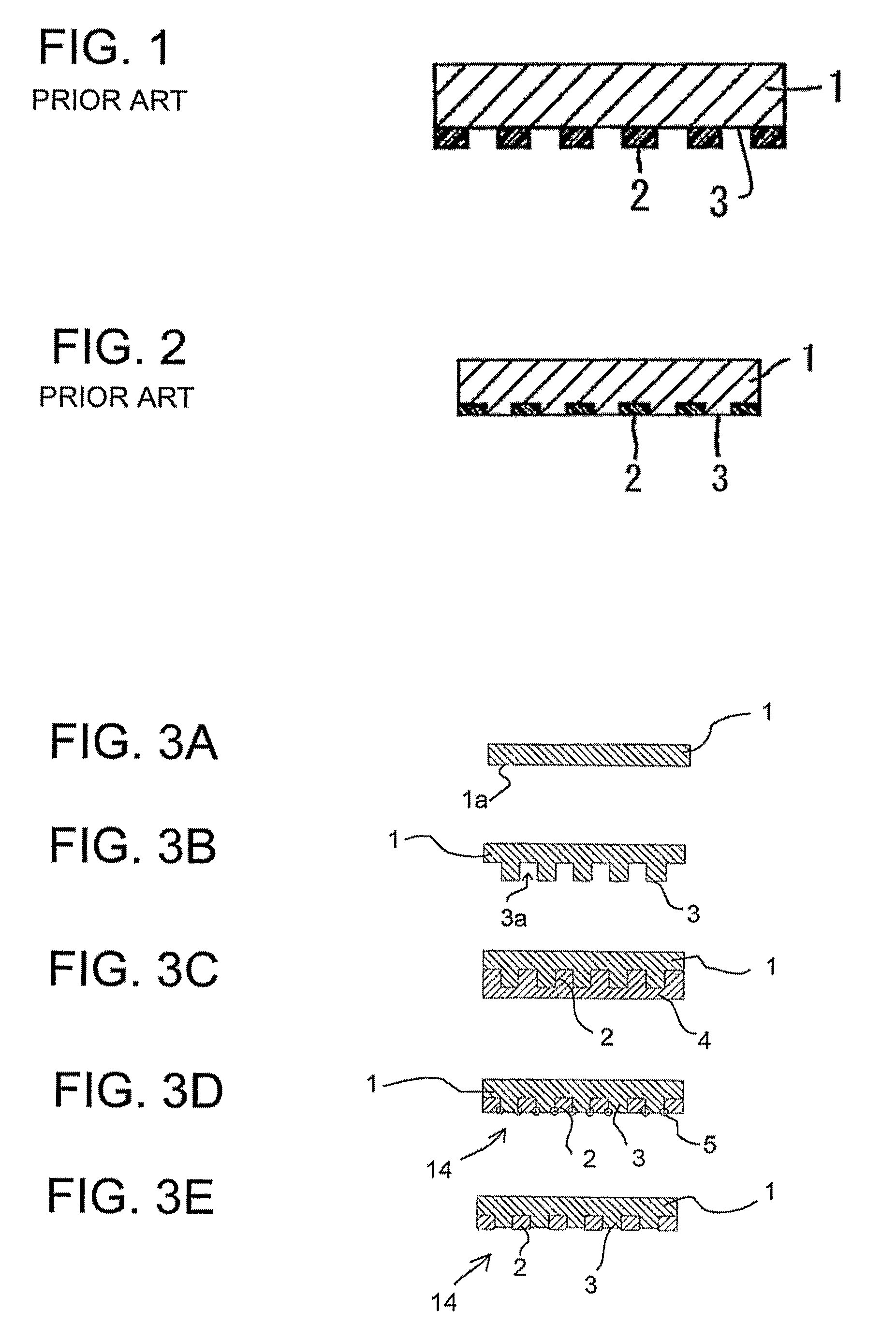
[0032]Referring to FIGS. 3A-3E, a process for forming an electrode tool for electrochemical machining according to the present invention will now be described.

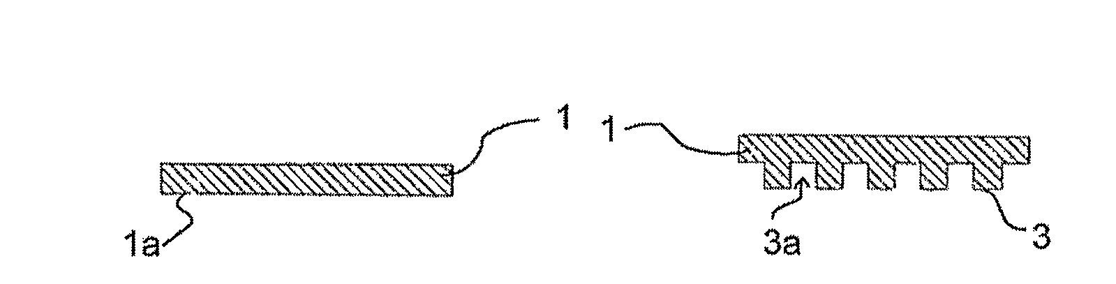
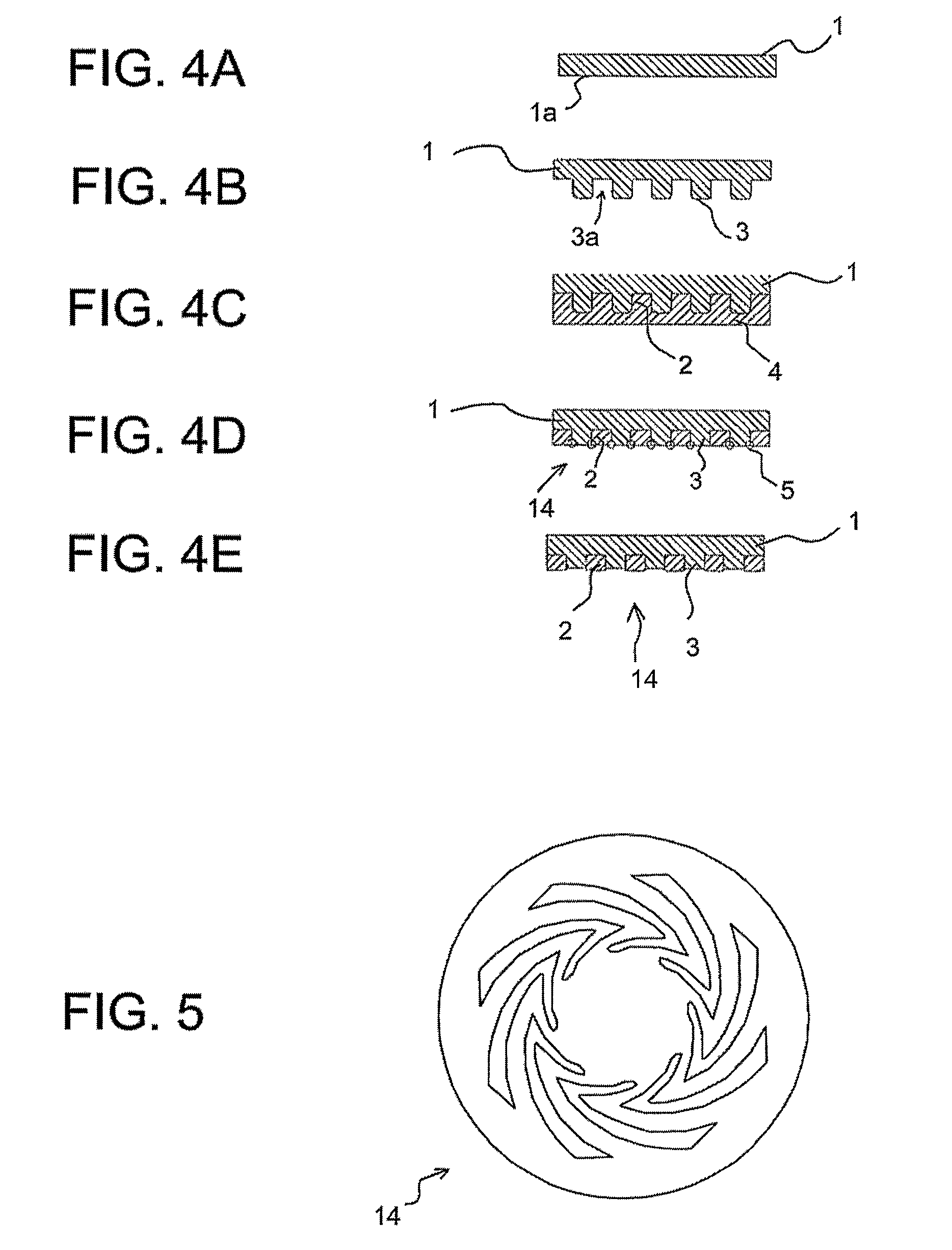
[0033]In FIG. 3A, an electrode substrate 1, which is formed preferably from copper alloy brass, includes a surface 1a that is used as a machining electrode. The machining electrode surface 1a is washed, and, as shown in FIG. 3B, lands 3 are then milled on the surface 1a by groove machining. The lands 3 together form a conductive pattern, such as the conductive pattern 14 shown in FIG. 5. After the conductive pattern 14 is formed, the machining electrode surface 1a is degreased and washed.

[0034]Next, as shown in FIG. 3C, the top of the machining electrode surface 1a is molded with epoxy resin to form a hard insulating resin layer 4. The hard insulating resin layer 4 is polished by a polishing machine to gradually thin it until, as shown in FIG. 3D, the conductive pattern 14 becomes visible therethrough, with insulating resin 2 ...

second embodiment

[0036]An electrode tool for electrochemical machining according to the present invention may be fabricated by the process illustrated in FIGS. 4A-4E.

[0037]In the second embodiment, copper alloy brass is used as the electrode substrate 1. As shown in FIG. 4A, the surface 1a to be used as the machining electrode is washed. Next, as shown in FIG. 4B, lands 3 are milled on the surface 1a of the electrode substrate by groove machining to form the conductive pattern 14 shown in FIG. 5. After the conductive pattern 14 is formed, the edges of the lands 3 that jut into adjacent grooves 3a are rounded, and the surface 1a of the machining electrode is washed.

[0038]As shown in FIG. 4C, the surface 1a of the machining electrode is molded with epoxy resin to form a hard insulating resin layer 4 over the machining electrode. The hard insulating resin layer 4 is then removed by polishing, and an insulating resin 2 remains in the grooves after polishing. The hard insulating resin layer 4 is graduall...

third embodiment

[0040]An electrode tool for electrochemical machining according to the present invention may also be fabricated by the process illustrated in FIGS. 4A-4E.

[0041]Specifically, an austenitic stainless steel SUS 304 is used as the electrode substrate 1. The surface to be used as the machining electrode is washed. As shown in FIG. 4B, groove machining of the surface of the machining electrode by laser machining is performed to form the lands 3. The lands 3 together form an electrode conductive pattern 14 such as that shown in FIG. 5.

[0042]After formation of the conductive pattern 14, the edges of the lands 3 that jut into the grooves 3a are rounded, and the machining surface is degreased and washed. As shown in FIG. 4C, the surface 1a of the machining electrode is molded with epoxy resin to form a hard insulating resin layer 4. The hard insulating resin layer 4 is polished and gradually thinned it until, as shown in FIG. 4D, the conductive pattern 14 becomes visible. Almost no burring oc...


PUM

PropertyMeasurementUnit
heightaaaaaaaaaa
heightaaaaaaaaaa
heightaaaaaaaaaa

Abstract

An electrode tool for electrochemical machining includes a machining electrode surface (1a). The machining electrode surface (1a) includes a conductive pattern defined by lands (3) and grooves (3a) that are formed by groove machining the electrode surface (1a). The machining electrode surface (1a) is then molded with a hard insulating resin layer (4), and a surface of the hard insulating resin layer (4) is mechanically polished to expose the lands (3) of the conductive pattern. The lands (3) are chemically dissolved to obtain a conductive pattern (14) having a surface that is formed below a resulting insulating resin surface (2), with the height difference between the two surfaces being between 1 and 5 μm. The electrode tool allows precise surface machining of work pieces and can withstand prolonged use.

Description

CROSS REFERENCE TO RELATED APPLICATION[0001]This application is a 371 of PCT / US04 / 42595 filed on Dec. 21, 2004, and claims priority from Japanese Patent Application No. 2004-015934, which was filed on Jan. 23, 2004.BACKGROUND OF THE INVENTION[0002]The present invention relates to an electrode tool for electrochemical machining, and to a method of manufacturing the electrode tool. More specifically, the present invention relates to an electrode tool that is capable of performing electrochemical machining of dynamic pressure generating grooves in fluid bearings with a high degree of precision over long periods of time.[0003]A dynamic groove machining device is utilized to form dynamic grooves on the surface of a work piece such as a fluid bearing. The dynamic grooves generate dynamic pressure on bearing fluid located between the bearing and a shaft to support the shaft within the bearing. As shown in FIG. 1, a conventional electrode tool for dynamic groove machining includes an electr...

Claims


Application Information

Patent Timeline
Patent Type & Authority Patents(United States)
IPC IPC(8): B23H3/00C25D17/10
CPCC25D17/10Y10T29/49639Y10T29/5122Y10T29/49117
Inventor YASUDA, TOMOYUKIIDE, MAKOTO
Owner MINEBEAMITSUMI INC
Why Eureka
Try Eureka