Hybrid passive optical network

Inactive Publication Date: 2006-07-13
SAMSUNG ELECTRONICS CO LTD
View PDF4 Cites 48 Cited by
  • Summary
  • Abstract
  • Description
  • Claims
  • Application Information

AI Technical Summary

Benefits of technology

[0012] The present invention is directed to substantially solving at least the above problems and/or disadvantages. Accordingly, an object of the present inventio

Problems solved by technology

However, the hybrid WDM-PON

Method used


Image

  • Hybrid passive optical network
  • Hybrid passive optical network
  • Hybrid passive optical network

Examples


Embodiment Construction

[0022] In the following discussion, details of well-known functions or constructions are omitted for clarity of presentation.

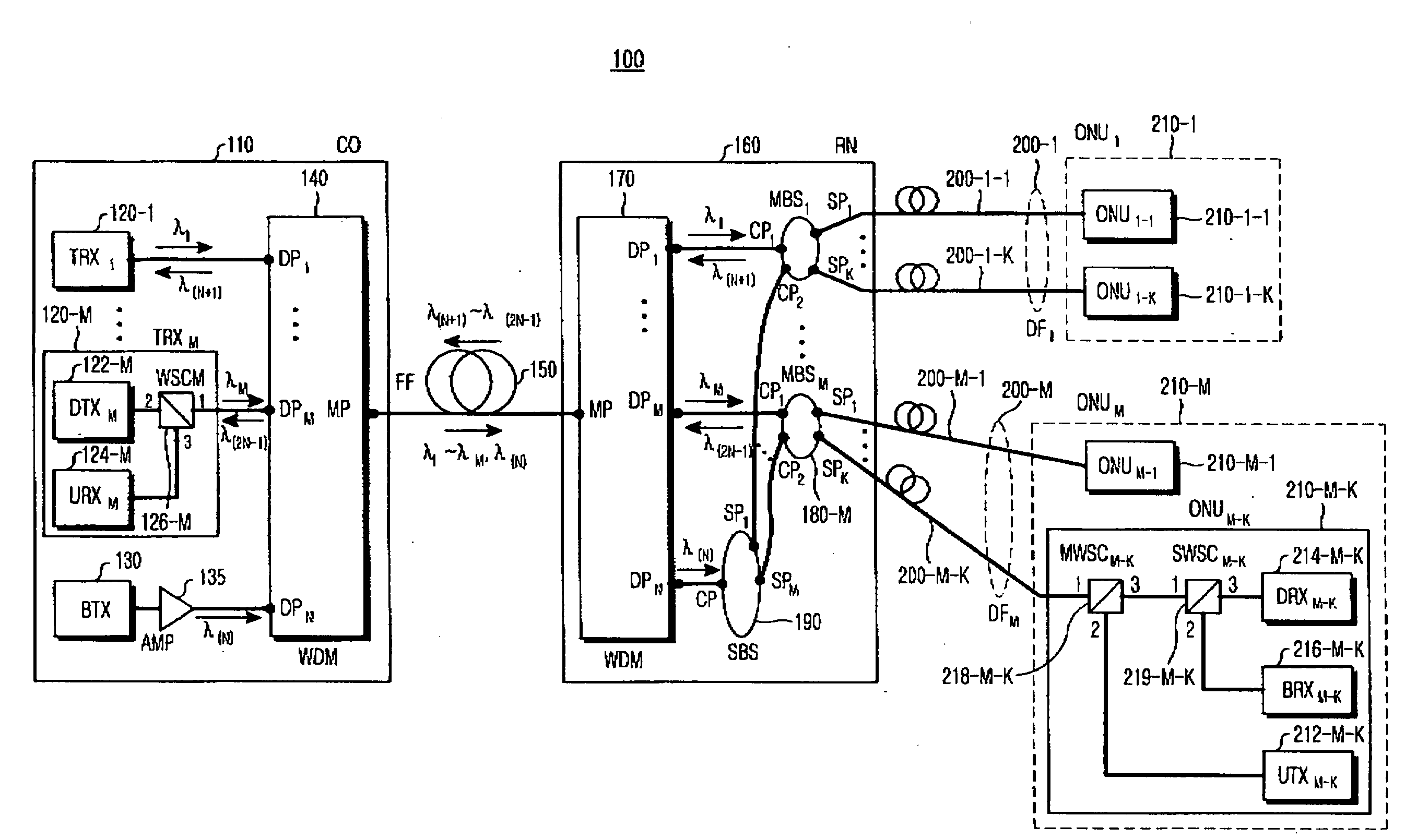
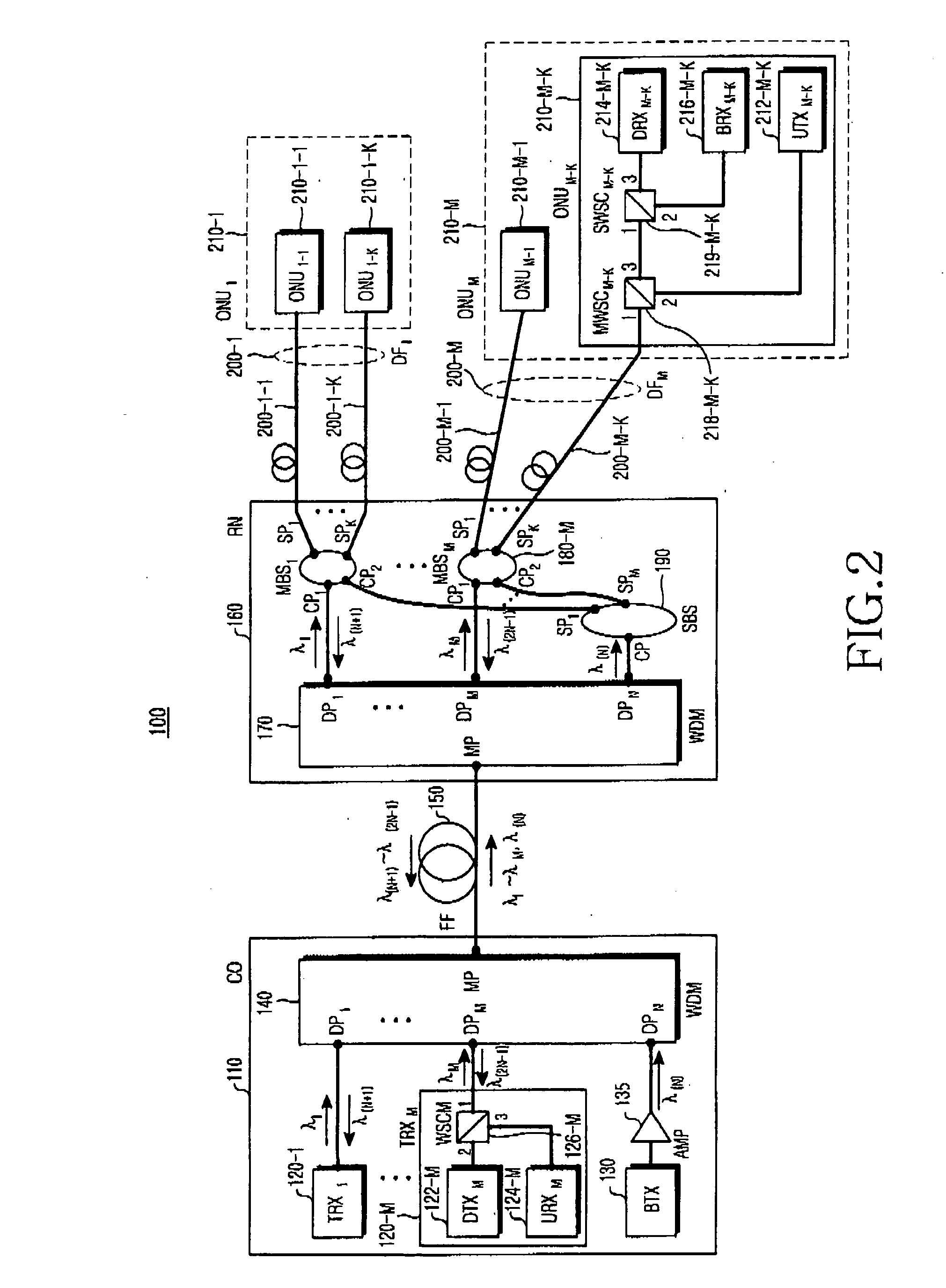
[0023]FIG. 2 is a block diagram showing, by way or illustrative and non-limitative example, a hybrid wavelength division multiplexing / time division multiplexing passive optical network (WDM / TDM-PON) 100 according to a first preferred embodiment of the present invention. Referring to FIG. 2, the hybrid WDM / TDM-PON 100 includes a central office (CO) 110, a remote node (RN) 160 connected to the CO 110 using a feeder fiber (FF) 150, first to M*Kth optical network units (ONUs) 210-1-1 to 210-M-K connected to the RN 160 on a point-to-point basis using first to M*Kth distribution fibers (DFs) 200-1-1 to 200-M-K, where M and K are predetermined natural numbers. The CO 110 multiplexes and transmits first to Mth downstream optical signals for communication. The CO 110 also multiplexes and transmits an Nth downstream optical signal for broadcasting and receives a multip...


PUM


Abstract

A hybrid passive optical network (PON) includes a central office (CO) for multiplexing at least one downstream optical signal for broadcasting and a plurality of downstream optical signals for communication. The PON further includes a remote node (RN) connected to the CO using at least one feeder fiber (FF), and a plurality of optical network units (ONUs), each connected to the RN using at least one distribution fiber (DF). The RN demultiplexes the multiplexed downstream optical signal received from the CO into the downstream optical signal for broadcasting and the downstream optical signals for communication, and multi-splits the downstream optical signal for broadcasting. The RN transmits each split broadcasting downstream optical signal and its corresponding downstream optical signal for communication to each ONU.

Description

CLAIM FOR PRIORITY [0001] This application claims priority under 35 U.S.C. §119 to an application entitled “Hybrid Passive Optical Network,” filed in the Korean Intellectual Property Office on Jan. 12, 2005 and assigned Serial No. 2005-2943, the contents of which are incorporated herein by reference. BACKGROUND OF THE INVENTION [0002] 1. Field of the Invention [0003] The present invention relates generally to a passive optical network (PON), and in particular, to a hybrid PON supporting communication and broadcasting services. [0004] 2. Description of the Related Art [0005] A passive optical network (PON) is a communication network in which a central office (CO) is connected to optical network units (ONUs) using optical fibers to transceive information based on optical signals. The signals can accommodate broadcasting, very high speed information, and additional communication services desired by a subscriber. In general, a PON has a star structure in which the CO is connected to eac...

Claims


Application Information

Patent Timeline
IPC IPC(8): H04J14/00H04B10/2581
CPCH04J14/0226H04J14/0227H04J14/0282H04J14/0298H04J14/0246H04J14/0247H04J14/025H04J14/0252G02B6/28H04B10/2581
Inventor PARK, SUNG-BUMSHIM, CHANG-SUPHWANG, SEONG-TAEK
Owner SAMSUNG ELECTRONICS CO LTD
Why Eureka
Try Eureka