Monitoring apparatus

a technology of monitoring apparatus and monitoring body, which is applied in the field of monitoring apparatus, can solve the problems of increasing the cost disfiguring the design of the monitoring camera body, and troublesome installation personnel, and achieves the effect of easy grasping the operation state of the apparatus, not disfiguring the design, and inexpensive structur

Inactive Publication Date: 2011-04-21
SONY CORP
View PDF4 Cites 18 Cited by
  • Summary
  • Abstract
  • Description
  • Claims
  • Application Information

AI Technical Summary

Benefits of technology

[0011]In light of the foregoing, it is desirable to provide a novel and improved monitoring apparatus, with an inexpensive structure, that allows a caretaker or the like to easily grasp the operation state of the apparatus, without disfiguring the design of the apparatus.
[0018]As described above, according to the embodiments of the present invention, it is possible to allow a caretaker or the like to easily grasp the operation state of the apparatus, by providing the apparatus having an inexpensive structure and whose design is not disfigured.

Problems solved by technology

There is an issue that it is troublesome for the installation personnel or the like to remove the body front cover every time the operation state of the monitoring camera is to be verified.
There also exists an issue that the cost of the body of the monitoring camera increases when a light guide tube is used in order to allow the light-emitting state of the LED placed inside the body of the monitoring camera to be verified from outside of the monitoring camera.
Furthermore, there was an issue that the design of the body of the monitoring camera was disfigured when a peephole for verification of the light-emitting state of the LED was formed on the body front cover of the monitoring camera in order to allow the light-emitting state of the LED placed inside the body of the monitoring camera to be verified from outside of the monitoring camera.

Method used


Image

  • Monitoring apparatus
  • Monitoring apparatus
  • Monitoring apparatus

Examples


first embodiment

1. Outer appearance example of monitoring camera (first embodiment)

2. Configuration example of monitoring camera (first embodiment)

second embodiment

3. Another configuration example of monitoring camera (second embodiment)

[Outer Appearance Example of Monitoring Camera]

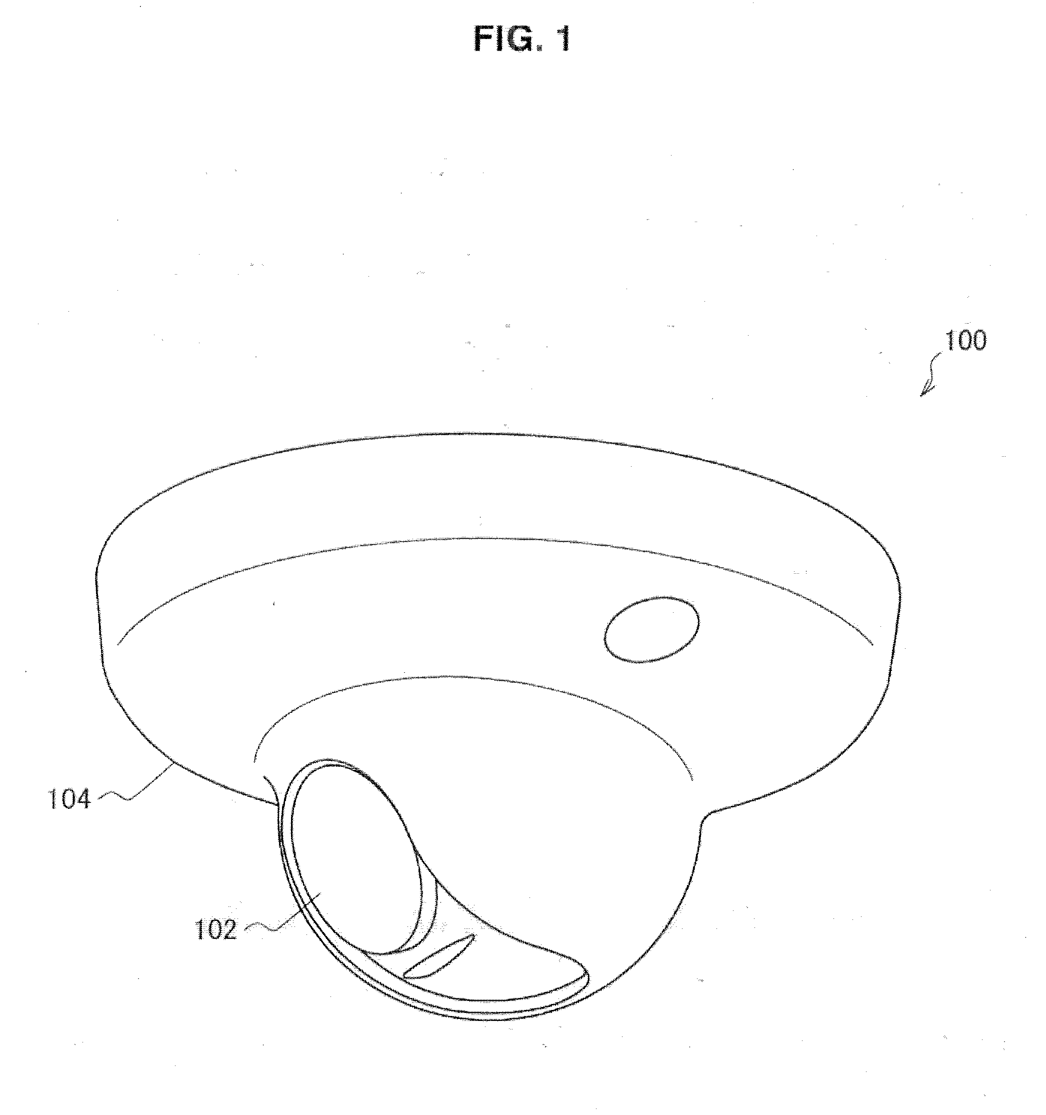
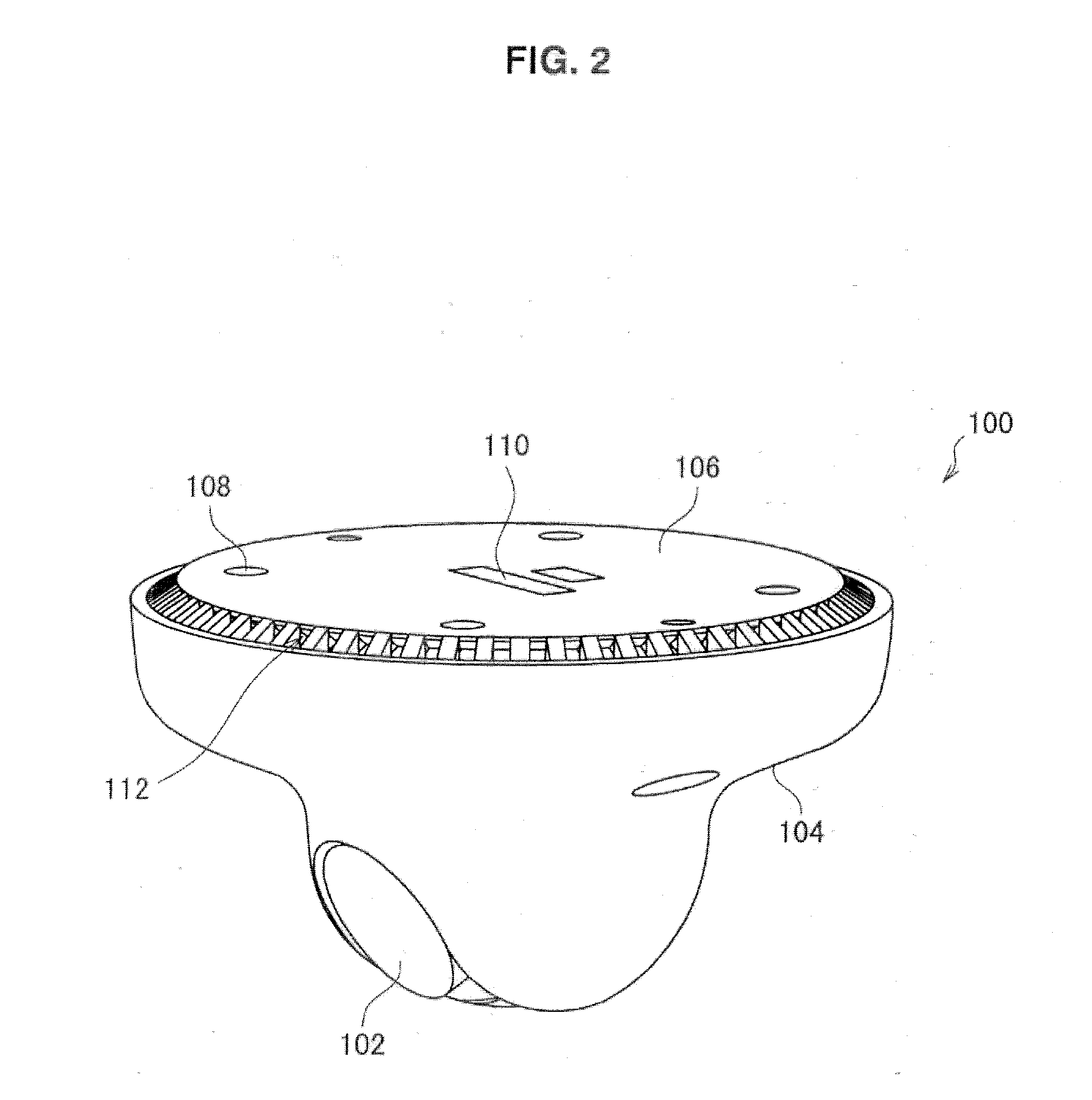
[0026]First, an outer appearance example of a monitoring camera according to a first embodiment will be explained. FIG. 1 is a perspective view illustrating the outer appearance of the monitoring camera viewed obliquely from below according to the first embodiment of the present invention. FIG. 2 is a perspective view illustrating the outer appearance of the monitoring camera viewed obliquely from above according to the first embodiment of the present invention.

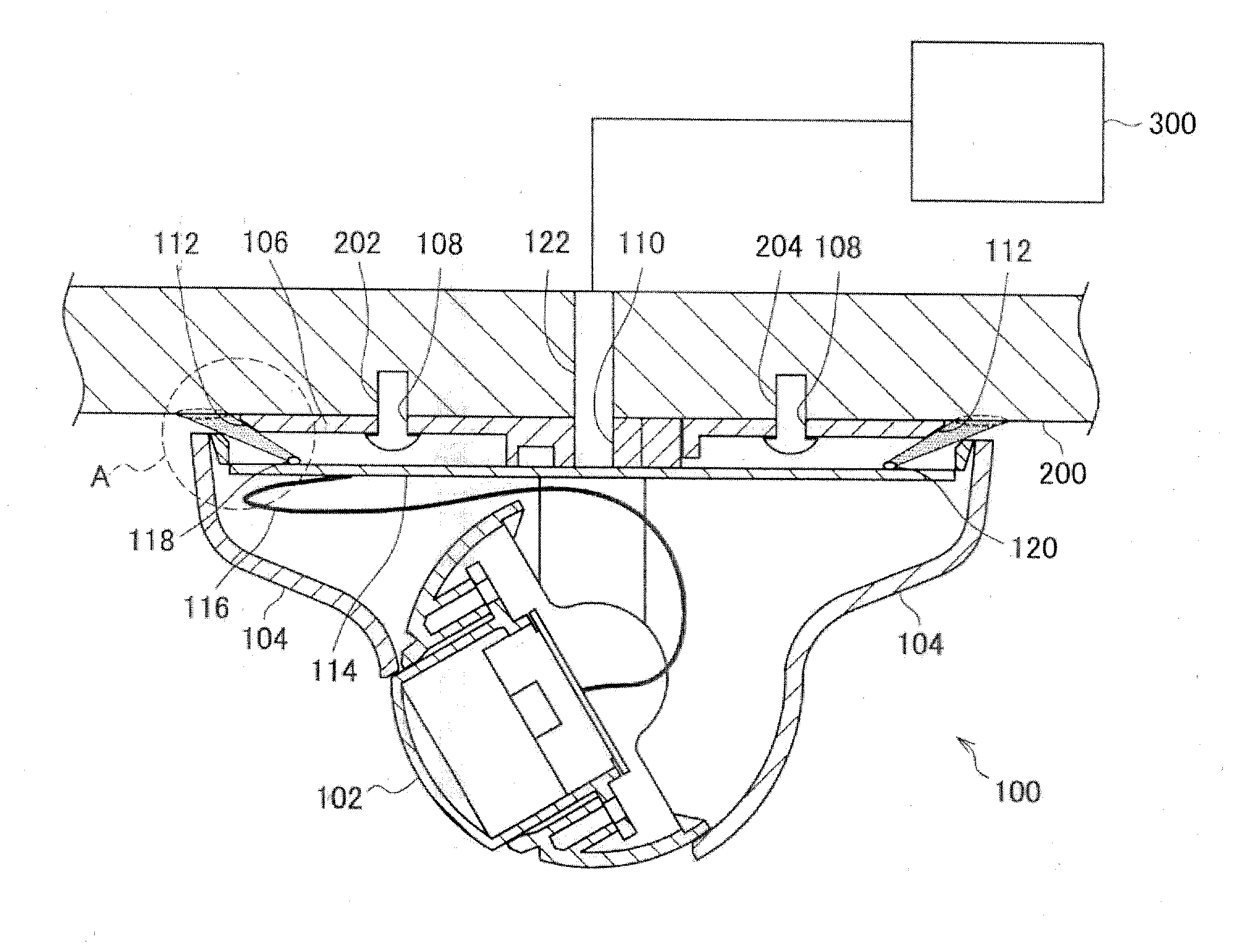
[0027]In FIG. 1 and FIG. 2, a monitoring camera 100 is shown as an example of the monitoring apparatus according to the first embodiment of the present invention, and includes mainly a camera module 102, a body front cover 104, and a body rear cover 106.

[0028]The camera module 102 has an imaging element (not shown), and captures a subject image to generate an image signal. The body front cover 104 is in the ...


PUM


Abstract

There is provided a monitoring apparatus including a front cover, an imaging device that is accommodated in the front cover and captures a subject image, a rear cover to be fixed onto a mounting surface on which the apparatus is mounted, and an emitting unit that emits light toward the mounting surface, where a light-emitting state of the light emitted by the emitting unit is associated with an operation state of the apparatus.

Description

BACKGROUND OF THE INVENTION[0001]1. Field of the Invention[0002]The present invention relates to a monitoring apparatus.[0003]2. Description of the Related Art[0004]As a related art, a monitoring camera is proposed as a monitoring apparatus that is placed on a ceiling or the like of a building or a room and that monitors surroundings of the building or the inside of the room (see JP 2005-311826 A, for example).[0005]It is necessary for installation personnel or the like of such a monitoring camera to grasp the operation state of the monitoring camera and to verify whether the monitoring camera is operating normally after installing the monitoring camera.[0006]The monitoring camera changes a light-emitting state of the light-emitting diode (LED), which is placed on a board inside the body, in association with an operation state of the monitoring camera, for example. This allows the installation personnel or the like of the monitoring camera to grasp the operation state of the monitor...

Claims


Application Information

Patent Timeline
Patent Type & Authority Applications(United States)
IPC IPC(8): H04N5/225
CPCH04N5/2256H04N5/2252H04N23/56H04N23/51
Inventor OOMORI, TAKAYOSHI
Owner SONY CORP
Why Eureka
Try Eureka