Image formation device and image formation method

a technology of image formation device and image, which is applied in the field of image forming apparatus and image forming method, can solve the problems of image distortion, image stripe lines, and image definition deterioration, and achieve the effects of reducing the number of images

Inactive Publication Date: 2006-07-13
PANASONIC CORP
View PDF3 Cites 2 Cited by
  • Summary
  • Abstract
  • Description
  • Claims
  • Application Information

AI Technical Summary

Benefits of technology

[0025] Further, an image forming apparatus of the present invention comprises: a recording intermediate belt which does not have an end; a platen drum and at least one roller around which the recording intermediate belt loops so as to be revolvable; a dyeing layer formation section for forming a dyeing layer on an outer surface of the revolving recording intermediate belt by thermocompression bonding; a plurality of image formation sections which are located downstream of the dyeing layer formation section in the revolving direction of the recording intermediate belt, and which transfer dyes of different colors to the dyeing layer formed on the outer surface of the recording intermediate belt to form a color image; an image transfer section for transferring the dyeing layer on which an image of the image formation sections is formed to recording paper by thermocompression bonding; a separation roller which is provided downstream of the image transfer section in the revolving direction of the recording intermediate belt, and which guides the recording intermediate belt and the recording paper, which are pressure-bonded to each other via the dyeing layer and moving, in different directions to separate the recording intermediate belt and the recording paper from each other; and cutting means for cutting the recording paper guided in a different direction from the recording intermediate belt by the separation roller into color images which have been formed, wherein the cutting means is located such that the recording paper bends to an extent to absorb a cutting shock generated when the recording paper is cut by the cutting means.
[0026] Further, an image forming apparatus of the present invention comprises: a recording intermediate belt which does not have an end; a platen drum and at least one roller around which the recording intermediate belt loops so as to be revolvable; a dyeing layer formation section for forming a dyeing layer on an outer surface of the revolving recording intermediate belt by thermocompression on bonding; a plurality of image formation sections which are located downstream of the dyeing layer formation section in the revolving direction of the recording intermediate belt, and which transfer dyes of different colors to the dyeing layer formed on the outer surface of the recording intermediate belt to form a color image, an image transfer section for transferring the dyeing layer on which an image of the image formation sections is formed to recording paper by thermocompression bonding; and a control section for outputting control signals for respectively controlling the image formation sections based on an input image signal which has been input, wherein the control section calculates a processing time of an input image signal which is input for each of images to be formed when images are formed continuously, and, based on the calculated results, sets an order for forming the images.
[0027] In the image forming apparatus of the present invention, it is preferable that the control section sets an order for forming images such that images having processing times for input image signals which are input are longer than a pre-set reference value are not continuously formed.
[0028] In the image forming apparatus of the present invention, it is preferable that the control section performs based on calculated results of calculation on a processing time of an input image signal which is input, a process of input image signal of an image having a processing time for an input image signal longer than a pre-set reference value before forming an image.
[0029] Further, an image forming apparatus of the present invention comprises: a recording intermediate belt which does not have an end; a platen drum and at least one roller around which the recording intermediate belt loops so as to be revolvable; a dyeing layer formation section for forming a dyeing layer on an outer surface of the revolving recording intermediate belt by thermocompression bonding; a plurality of image formation sections which are located downstream of the dyeing layer formation section in the revolving direction of the recording intermediate belt, and which transfer dyes of different colors to the dyeing layer formed on the outer surface of the recording intermediate belt to form a color image; an image transfer section for transferring the dyeing layer on which an image of the image formation sections is formed to recording paper by thermocompression bonding; and a control section for outputting control signals for respectively controlling the image formation sections based on an input image signal which has been input, wherein the control section is set to calculate a processing time of an input image signal which is input for each of images to be formed, and to perform a process of an input image signal of an image having a processing time for an input image signal longer than a pre-set reference value when an image formation operation is suspended for radiating heat from a high-temperature state caused by continuously performing image formation operations.

Problems solved by technology

However, in the image forming apparatuses employing this dye thermal transfer method, there is a problem that, when the recording heads do not press the dyeing layer on the recording intermediate belt at the correct locations with correct pressing strength, distortion of images such as stripe lines on images occur, and definition of the images tend to deteriorate.
Further, such distortions in the images may also be generated by load changes when the step of cutting the recording paper with the dyeing layer transferred thereto into pieces of a predetermined size by a cutter after it is removed from the recording intermediate belt is performed.
If image quality is deteriorated due to such image distortions, a plurality of images cannot be formed at the same time, and thus, the efficiency of image formation cannot be promoted.
Further, in the above-describe image forming apparatuses, if the size of images to be formed increases, a long time is required as image process operation time for generating a control signal for forming images.
Due to the image process operation time, a blank image may be formed since the control signal cannot be in time to start image formation.
Thus, the efficiency of image formation cannot be promoted.

Method used


Image

  • Image formation device and image formation method
  • Image formation device and image formation method
  • Image formation device and image formation method

Examples


embodiment 1

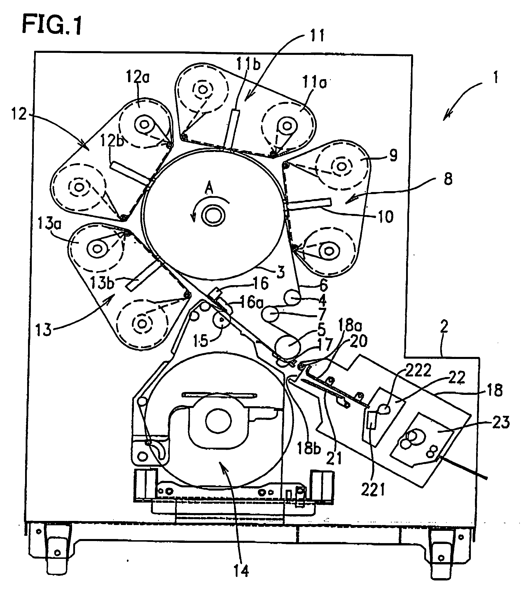
[0063] In Embodiment 1, an image forming apparatus having a structure in which a load change due to joints of a recording intermediate belt 6 does not have an influence will be described.

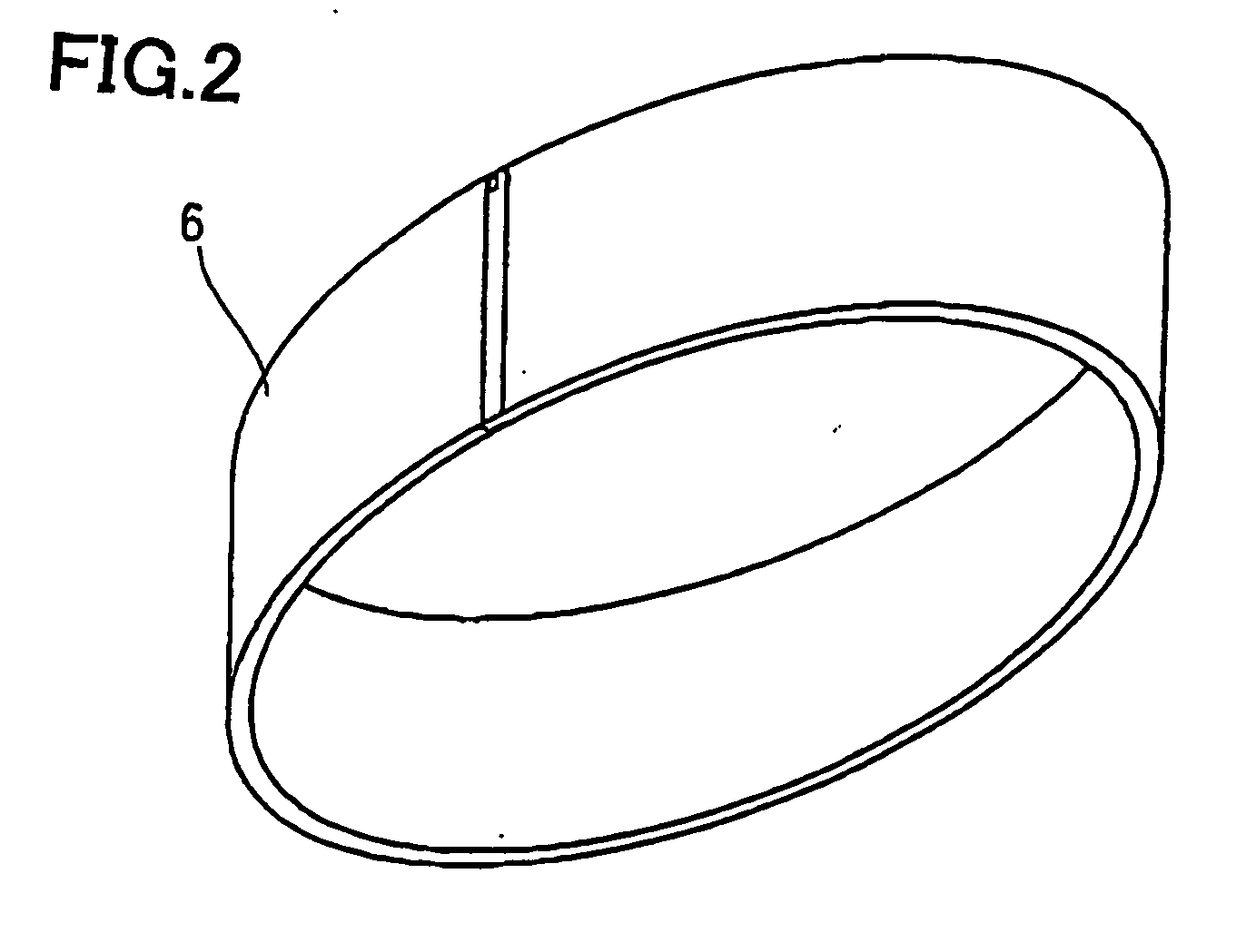
[0064] As described above, the recording intermediate belt 6 used in the image forming apparatus 1 is formed without an end by coupling ends of the belt body having a band shape. Thus, when a seam of the recording intermediate belt 6 passes by the dyeing layer transfer head 10 of the dyeing layer formation section 8 or the recording heads 11b through 13b of the image formation sections 11 through 13, if the dyeing layer transfer head 10 or the recording heads 11b through 13b press the seam portion, a load change occurs in the platen drum 3. If an image is formed at another image formation section at the time, image quality thereof is degraded due to an influence of the load change.

[0065] In the image forming apparatus 1 of Embodiment 1, the recording heads 11b through 13b of the image formation se...

embodiment 2

[0073] In Embodiment 2, an image forming apparatus having a structure for avoiding defective image formation at the seam portion of the recording intermediate belt 6.

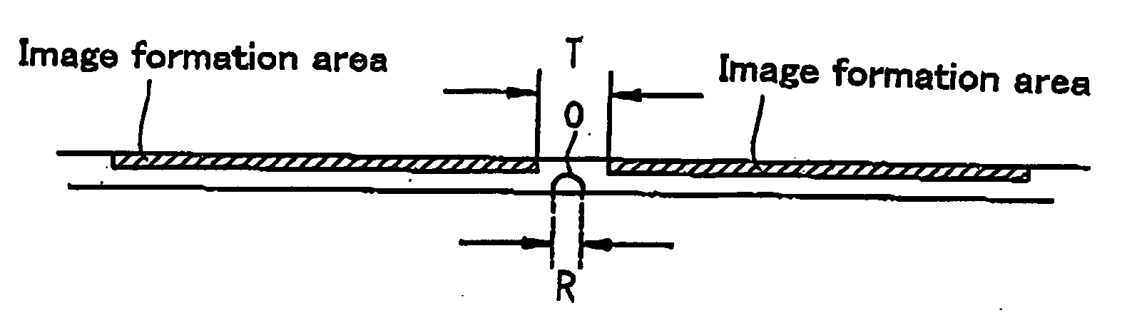
[0074] As described above, the recording intermediate belt 6 used in the image forming apparatus 1 is formed without an and by coupling the ends of the belt body having a band shape. Thus, the seam portion of the recording intermediate belt 6 has a thermal conductivity different from that of other portions of the recording intermediate belt 6. If the dyeing layer is formed on the seam portion, and the recording heads 11b through 13b are pressed to this portion to dye with the dyes of each color, the image quality of this portion becomes different from the image quality of other portions. Thus, in order to form high-definition images, the seam portion should not be included in the image formation areas.

[0075] In the image forming apparatus 1 of Embodiment 2, as shown in FIG. 7, a mark 20 is printed at the position near...

embodiment 3

[0076] In Embodiment 3, an image forming apparatus having a structure which allows skipping a time required for starting image formation while avoiding defective image formation at the seam portion of the recording intermediate belt 6.

[0077] As described above, the recording intermediate belt 6 used in the image forming apparatus is formed without an end by coupling the ends of the belt body having a band shape. Thus, the seam portion of the recording intermediate belt 6 has a thermal conductivity different from that of other portions of the recording intermediate belt 6. If the dyeing layer is formed on the seam portion, and the recording heads are pressed to this portion to dye with the dyes of each color, only the image quality of this portion changes. Thus, in order to form high-definition images, the seam portion should not be included in the image formation areas.

[0078] In the image forming apparatus 1 of Embodiment 3, the recording intermediate belt 6 it revolved by driving...


PUM


Abstract

In order to avoid a load change which occurs when seam O passes by the heads affect image information, a dyeing layer transfer head and recording heads are located in equal intervals having length P, which is obtained by equally dividing an entire circumference K of a recording intermediate belt by n (n is integer), and, given that the position of the seam of the recording Intermediate belt, which does not have an end obtained by coupling two ends of a belt body of a band shape, is origin O, images are formed in portions except for portions at origin O, or at a distance of 1×P, 2×P, . . . (n−1)×P from origin O. In this way, it is possible to prevent deterioration in the image quality, such as a stripe line in an image formed by an image forming apparatus.

Description

TECHNICAL FIELD [0001] The present invention relates to an image forming apparatus and an image forming method for forming a full-color image on recording paper by a dye thermal transfer method. BACKGROUND ART [0002] One of image forming methods which can form an image having a high image quality comparable to the image quality of color pictures using a photograph development technique is a dye thermal transfer method (see, for example, Japanese Laid-Open Publication No. 2002-86776). The dye thermal transfer method is increasingly drawing attentions as digital cameras come into wide use since an image can conveniently formed based on digital image signals imaged by digital cameras. [0003] In the dye thermal transfer method, a dyeing layer, for example, a resin having a high pigment dyeing property on a base material, and dyes such as yellow, magenta, and cyan are sequentially pressed on and dyes the dyeing layer. The dyeing layer dyed with dyes of respective colors to transferred to...

Claims


Application Information

Patent Timeline
Patent Type & Authority Applications(United States)
IPC IPC(8): G03G16/00B41J3/407
CPCB41J3/407
Inventor MORITA, TETSUYASASAKI, KENJIWADA, TOSHIYUKIYAMASHITA, HARUOFUKUSHIMA, TSUMORU
Owner PANASONIC CORP
Why Eureka
Try Eureka