
Electronic device mounted on terminal equipment

a terminal equipment and electronic technology, applied in the field of electronic devices, can solve the problems of unjust reconstruction and inability to achieve sufficient security against unauthorized use, and achieve the effect of efficient authentication process and maintaining safety

Inactive Publication Date: 2006-07-13
KK TOSHIBA
View PDF10 Cites 27 Cited by
  • Summary
  • Abstract
  • Description
  • Claims
  • Application Information

AI Technical Summary

Benefits of technology

[0011] An object of this invention is to provide an electronic device, terminal equipment and communication system which can efficiently perform the authentication process while maintaining the safety.

Problems solved by technology

However, in the conventional system described above, there occurs a problem that it is impossible to attain sufficient security against unauthorized use based on unjust reconstruction of the terminal equipment or falsification of data in connection with multi-functionalization of the terminal equipment and diversification of services.

Method used


Image

  • Electronic device mounted on terminal equipment
  • Electronic device mounted on terminal equipment
  • Electronic device mounted on terminal equipment

Examples


Embodiment Construction

[0025] There will now be described preferred embodiments of this invention with reference to the accompanying drawings.

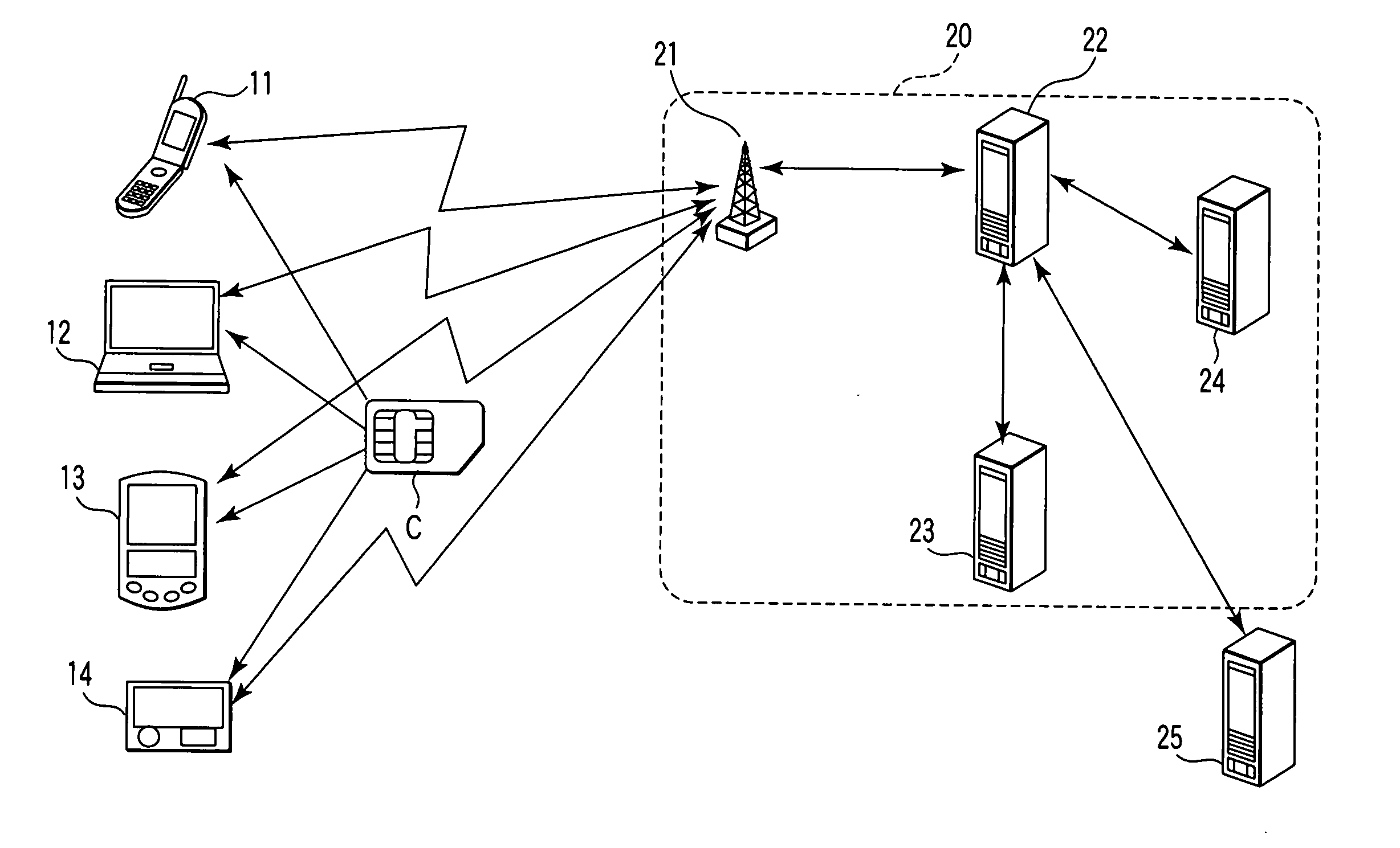
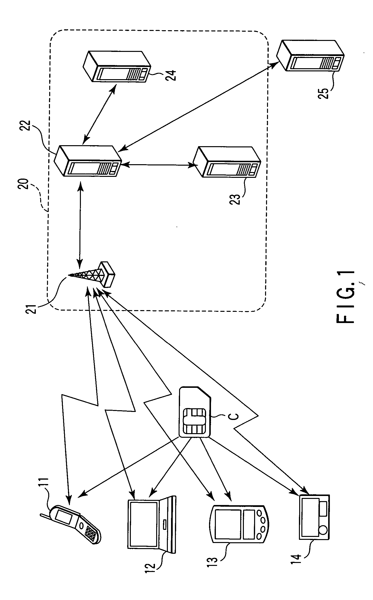
[0026]FIG. 1 is a view schematically showing an example of the configuration of a communication system including terminal equipment according to one embodiment of this invention.

[0027] In the communication system shown in FIG. 1, a mobile telephone 1 used as terminal equipment having an IC card C mounted thereon, a personal computer 12, a mobile information terminal (which is hereinafter referred to as a PDA) 13 and an electronic game machine 14 make communication with a system (communication company system) 20 of a communication company.

[0028] The IC card C is an electronic device including an LSI having a control element, memory and interface. The IC card C holds various control programs, data and the like. For example, authentication data, personal information of the user and the like are stored in the IC card. The IC card has a function of mutual authenticati...


PUM


Abstract

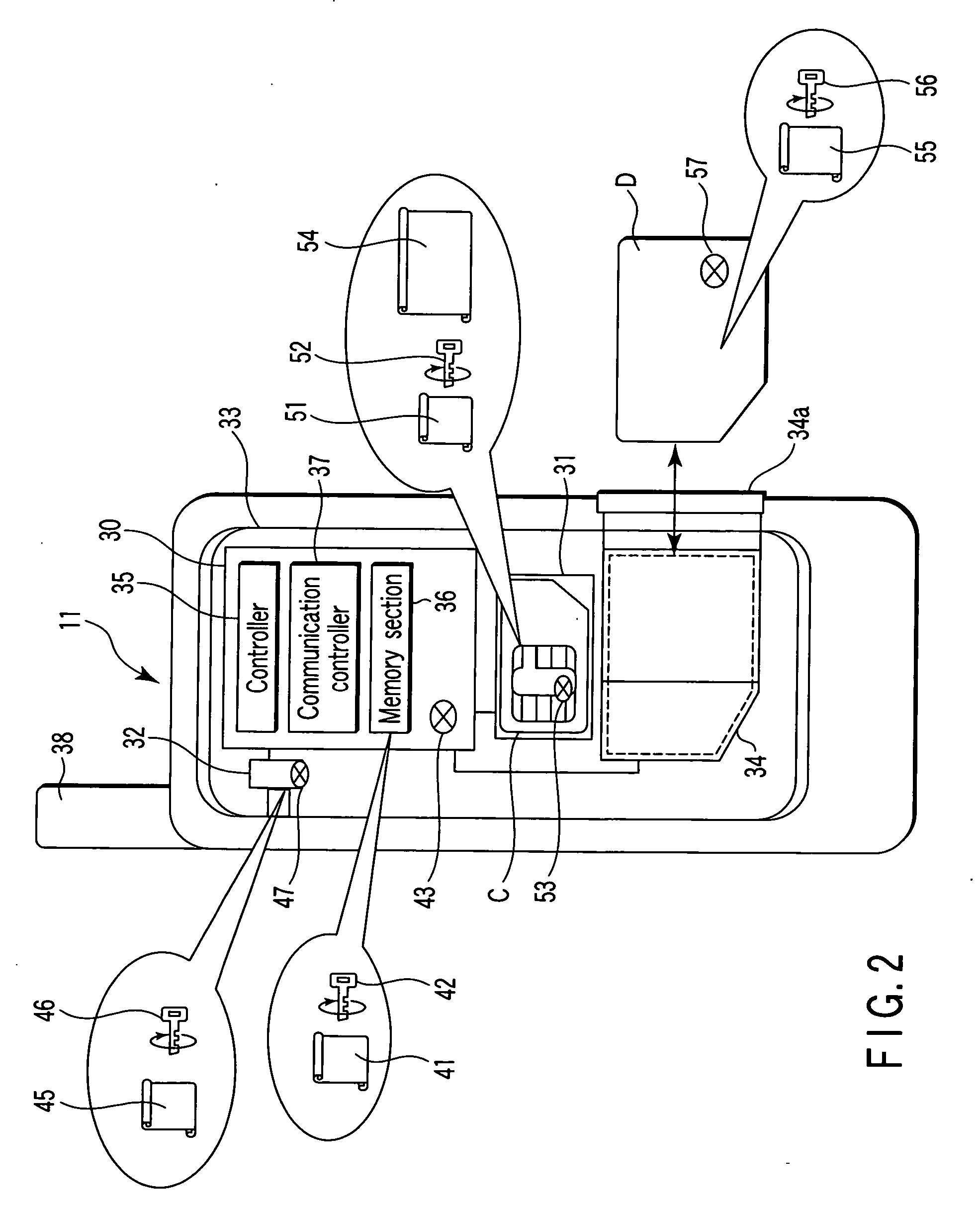
An IC card used as an electronic device mounted on terminal equipment performs a mutual authentication process for the main body of the terminal equipment. When mutual authentication for the IC card and the main body of the terminal equipment is successfully performed by the mutual authentication process, the IC card forms transmitting data to an external system containing information associated with the main body of the terminal equipment and information indicating the result of mutual authentication for the main body of the terminal equipment. The data containing information associated with the main body of the terminal equipment and information indicating the result of mutual authentication for the main body of the terminal equipment is transferred from the IC card to the external system via the main body of the terminal equipment when the IC card is authenticated by the external system.

Description

CROSS-REFERENCE TO RELATED APPLICATIONS [0001] This application is based upon and claims the benefit of priority from prior Japanese Patent Application No. 2005-006470, filed Jan. 13, 2005, the entire contents of which are incorporated herein by reference. BACKGROUND OF THE INVENTION [0002] 1. Field of the Invention [0003] This invention relates to an electronic device such as an. IC card mounted on a terminal equipment such as a mobile telephone having a communication function via a communication network, a terminal equipment on which the electronic device is mounted and a communication system, for example. [0004] 2. Description of the Related Art [0005] Recently, a system in which a communication company provides various services for the terminal equipment of the user has been proposed or put into practice. As one application form of the system, a system in which various services are provided from the communication company side for the terminal equipment on which an IC card having...

Claims


Application Information

Patent Timeline
IPC IPC(8): H04B1/38H04W8/18H04W88/02
CPCH04L63/0869H04M2250/14H04W8/183H04W12/06H04W88/02H04L63/0853H04W12/069A44B1/185F16B45/02A44D2211/00A41D2300/32
Inventor ISHIBASHI, TAKANOBU
Owner KK TOSHIBA
Learn More