Vacuum assisted auto-lancing device

a technology of assisted auto-lancing and vacuum, which is applied in the field of vacuum assisted auto-lancing devices, can solve the problems of increasing the burden on patients, increasing the cost of patients, and user experience considerable pain, so as to reduce anxiety and pain

Inactive Publication Date: 2006-07-13
CHA EUN JONG +4
View PDF3 Cites 106 Cited by
  • Summary
  • Abstract
  • Description
  • Claims
  • Application Information

AI Technical Summary

Benefits of technology

[0011] Accordingly, the present invention has been made keeping in mind the above problems occurring in the prior art, and an object of the present invention is to provide a vacuum assisted auto-lancing device, which is capable of drawing blood from a desired body site with a single operation regardless of the puncture site, and wh

Problems solved by technology

The method of drawing blood from the capillary vessels has been most widely used, but has a problem in that a patient must always carry the lancing device and a plurality of lancets.
However, the disposable auto-lancet is problematic in that manufacturing costs thereof increases, thus imposing an economic burden on patients.
Further, the conventional lancing device is problematic in that it is possible to draw blood only from a body site having many capillary vessels, for example, fingers or toes, so that a user experiences considerable pain due to nerve fibers which are distributed together with the capillary vessels, during the puncture of skin.
Thereby, the conventional lancing device or the disposable auto-lancet causes anxiety to the user, such as a chronic diabetic who draws blood every day.
However, the conventional vacuum assisted lancing device has a problem in that the plun

Method used


Image

  • Vacuum assisted auto-lancing device
  • Vacuum assisted auto-lancing device
  • Vacuum assisted auto-lancing device

Examples


Embodiment Construction

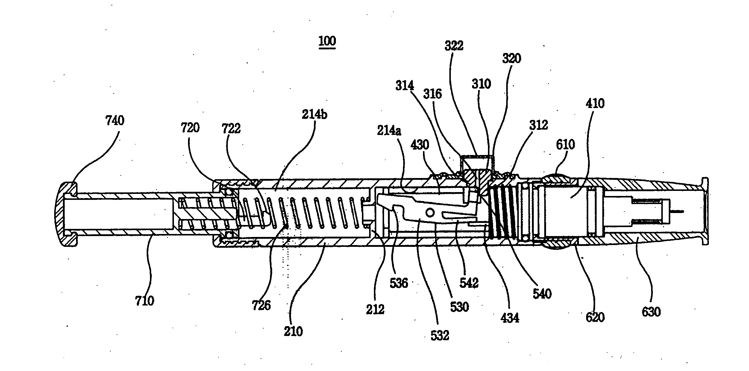
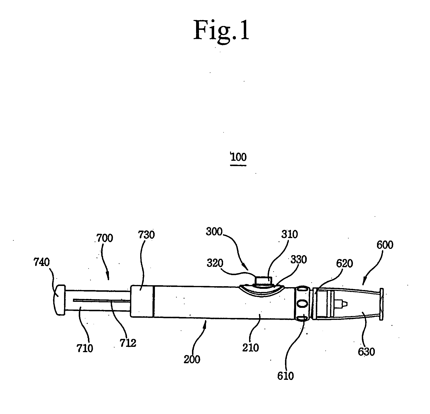
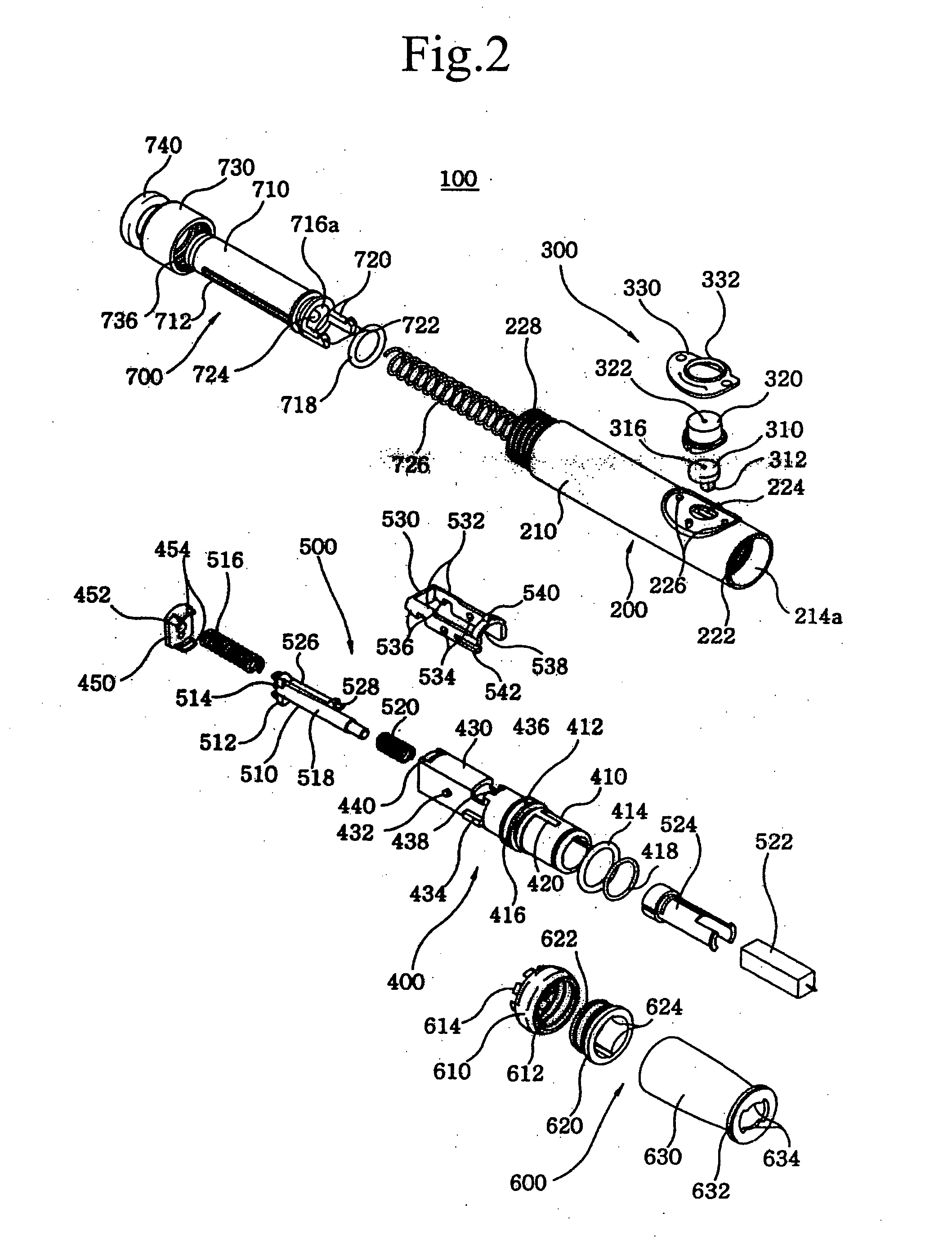
[0021] In order to accomplish the above object, the present invention provides a vacuum assisted auto-lancing device, including a housing having a body, the body being partitioned into a first chamber and a second chamber by a first partition plate, with a lever hole provided on an outer periphery of the first chamber at a position adjacent to a first end of the first chamber, and a locking protrusion vertically protruding from a position around the lever hole; an actuating lever including an actuating switch seated on the lever hole and having at a lower portion thereof first and second actuating steps which pass through the lever hole, a switch cap covering the actuating switch, and a switch cover locking the actuating switch and the switch cap to a predetermined position of the body; a holding unit including a first stem coupled at a first end thereof to an inner periphery of the first chamber, a second end of the first stem being exposed to an outside of the first chamber, a sec...


PUM


Abstract

Disclosed herein is a vacuum assisted auto-lancing device. The device includes a housing (200) having a body (210) which has a lever hole. An actuating lever (300) includes an actuating switch (310) seated on the lever hole and having first and second actuating steps, a switch cap (320), and a switch cover (330). The device also includes a holding unit (400) having a first stem (410), a second stem (430), and a stem cap (450). A trigger (500) has a first trigger unit activated by the first actuating step, and a second trigger unit activated by the second actuating step. A lancet holder (524) holding a lancet (522) is secured to an end of the first trigger unit. The device includes a blood collecting unit (600) having an adjusting screw, an adjusting slider, and an end cap, and a vacuum unit (700) having a plunger and a body cap.

Description

TECHNICAL FIELD [0001] The present invention relates, in general, to vacuum assisted auto-lancing devices and, more particularly, to a vacuum assisted auto-lancing device, which is capable of drawing blood from a desired body site with a single operation regardless of the puncture site, and which is constructed so that there is no need to re-adjust the depth of penetration of a lancet into the skin whenever the lancing device is used, and which is constructed to easily create a vacuum, thus alleviating fear and pain experienced by a user, therefore affording comfort to the user. BACKGROUND ART [0002] Generally, a chronic diabetic must perform self blood glucose monitoring at home daily to maintain constant blood glucose. In order to do a blood glucose test, a sample of blood must be drawn from a body site. For example, a disposable lancet is driven to puncture skin at a selected body site, such as fingers, thus drawing a small amount of capillary blood. The sample of blood is applie...

Claims


Application Information

Patent Timeline
IPC IPC(8): A61B5/00A61B5/15
CPCA61B5/1411A61B5/15186A61B5/150022A61B5/150099A61B5/150183A61B5/150236A61B5/150244A61B5/150259A61B5/150358A61B5/150412A61B5/15113A61B5/15117A61B5/1519A61B5/15194A61B5/1405
Inventor CHA, EUN JONGPARK, MI SOOKCUI, GANGNAM, HAK HYUNCHA, GEUN SIG
Owner CHA EUN JONG
Why Eureka
Try Eureka