Low noise pneumatic tire

a pneumatic tire and low noise technology, applied in inflatable tyres, non-skid devices, transportation and packaging, etc., can solve the problems of noise reduction, cavity resonance sound, tire noise, etc., and achieve the effect of reducing the cavity resonance sound of tires

Active Publication Date: 2006-07-20
YOKOHAMA RUBBER CO LTD
View PDF0 Cites 26 Cited by
  • Summary
  • Abstract
  • Description
  • Claims
  • Application Information

AI Technical Summary

Benefits of technology

[0017] According to a low noise pneumatic tire of the present invention, by forming a band-shaped sound absorbing material from a porous material and appropriately setting the apparent density defined in JIS K6400 for the porous material, and by attaching the porous material all around an entire circumference on an inner surface of a tread of the tire by use of an elastic fixing band, an effect of reducing tire cavity resonance sound is obtained through a sound absorption function realized all around the circumference by the porous material.

Problems solved by technology

One of the causes of tire noise is cavity resonance sound caused by vibration of air filled in the inside of a tire.
However, a full consideration has not been given to characteristics of the sound-absorbing material in this approach, and it is not necessarily considered that the approach has achieved an excellent result in noise reduction.

Method used


Image

  • Low noise pneumatic tire
  • Low noise pneumatic tire
  • Low noise pneumatic tire

Examples


examples

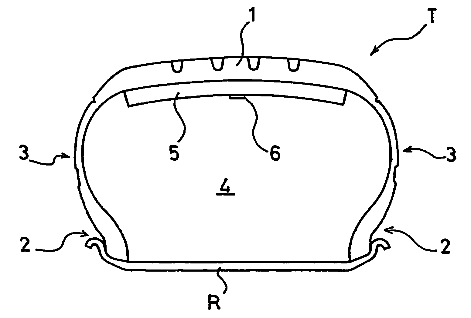
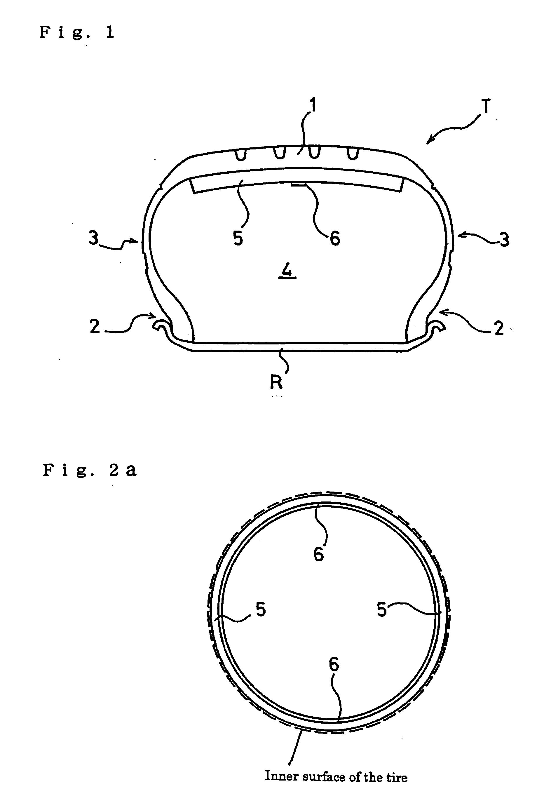
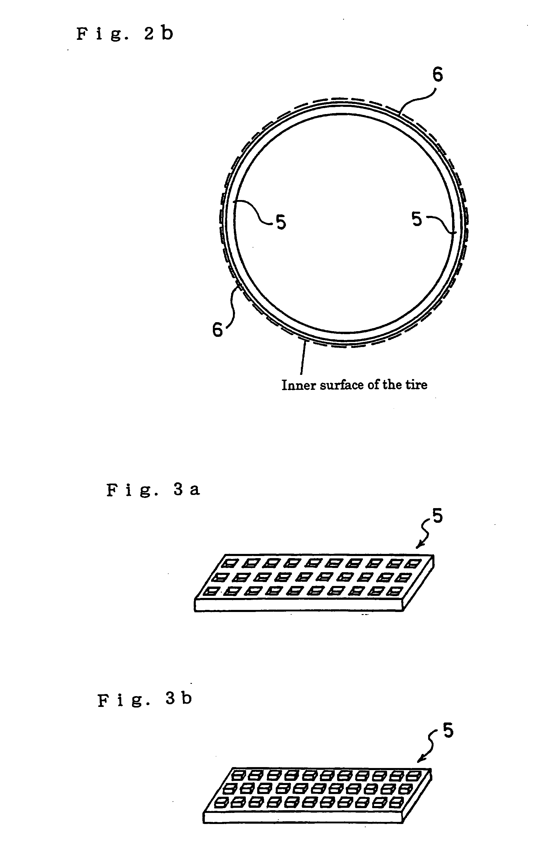
[0077] Pneumatic tires with a tire size of 205 / 65R15 were prepared respectively as: a conventional tire (Conventional Example) where nothing was attached in a cavity portion thereof and a tire of the present invention (Example) and comparative tires (Comparative Examples 1 and 2) respectively having sound absorbing materials attached in cavity portions thereof all around entire circumferences on inner surfaces of tread portions thereof as shown in FIG. 2a, the sound absorbing materials having apparent densities defined in JIS K6400 made different as shown in Table 1. Note that a width and a thickness of the sound absorbing materials were commonly set to 150 mm and 40 mm, respectively.

[0078] Test tires of each of the Examples were mounted onto wheels of a rim size of 15×6½ JJ respectively, and an air pressure thereof was set at 220 kPa, and then were installed to a passenger automobile having a displacement of 2500 cc. Then, a microphone was installed at a position corresponding to ...


PUM


Abstract

This invention provides a low noise pneumatic tire allowed to achieve an efficient noise reduction effect by making full use of characteristics of a sound absorbing material. A pneumatic tire according to the present invention is a low noise pneumatic tire where a band-shaped sound absorbing material formed of a porous material whose apparent density defined in JIS K6400 is in a range of 10 to 70 kg/m3, is attached on the inner surface of a tread by use of an elastic fixing band.

Description

TECHNICAL FIELD [0001] The present invention relates to a low noise pneumatic tire, and more specifically, relates to a low noise pneumatic tire allowed to effectively reduce noise caused by cavity resonance. BACKGROUND ART [0002] One of the causes of tire noise is cavity resonance sound caused by vibration of air filled in the inside of a tire. When the tire is rotated under a load, a ground-contacting portion in a tread portion of the tire vibrates because of irregularities on a ground surface and this vibration causes vibration of the air inside the tire and generates the cavity resonance sound. This cavity resonance sound is generated by vibration of air inside the tire caused by vibration of a ground-contacting portion in a tread portion of the tire which is generated by irregularities on a ground surface when the tire is rotated under a load. In this cavity resonance sound, it has been known that frequencies perceived as noise are approximately 200 to 250 Hz although they diff...

Claims


Application Information

Patent Timeline
Patent Type & Authority Applications(United States)
IPC IPC(8): B60C5/00B60C19/00
CPCB60C19/002Y10T152/10054Y10T152/10036Y10T152/10495Y10T152/10171B60C5/00B60C5/12B60C19/00
Inventor TANNO, ATSUSHIIKEDA, TOSHIYUKI
Owner YOKOHAMA RUBBER CO LTD
Why Eureka
Try Eureka