Methods and apparatus for an automatic temperature-controlled valve

a technology of automatic temperature control and valve body, which is applied in the direction of valve operating means/release devices, process and machine control, instruments, etc., can solve the problems of increasing water costs and heating costs, wasting a lot of water and energy each year, and simply losing a significant amount of hot water down the drain

Active Publication Date: 2006-07-20
AM CONSERVATION GRP
View PDF14 Cites 29 Cited by
  • Summary
  • Abstract
  • Description
  • Claims
  • Application Information

AI Technical Summary

Problems solved by technology

Because of this delay in receiving water at the correct temperature, vast amounts of water and energy are wasted each year.
That is, as most individuals are reluctant to stand by the shower and continuously monitor the water temperature for many minutes, a significant amount of hot water is simply lost down the drain.
This increases both water costs as well as heating costs.
Multiplied by the number of individuals that must engage in this practice on a daily basis, the waste from a conservation standpoint is staggering.

Method used


Image

  • Methods and apparatus for an automatic temperature-controlled valve
  • Methods and apparatus for an automatic temperature-controlled valve
  • Methods and apparatus for an automatic temperature-controlled valve

Examples


Embodiment Construction

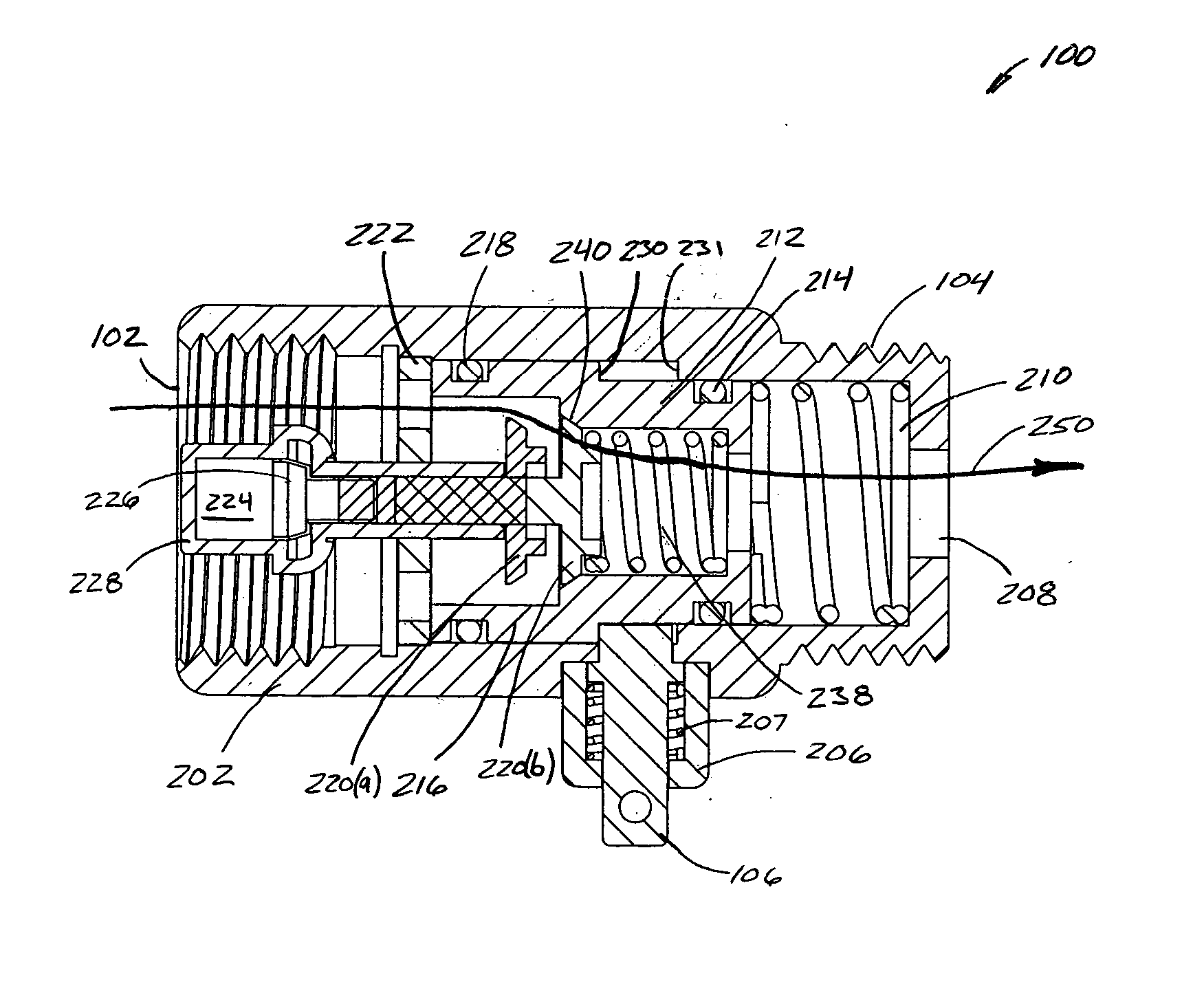
[0018] In general, the present invention relates to a valve, fitting, or any other such device (generally, a “valve”) that allows the flow of water to be terminated automatically when the water flowing through the device reaches a specific temperature. The flow may thereafter be released automatically or manually, depending upon the application. The technology may be used in a variety of contexts, including, for example, stand-alone consumer or commercial valves, embedded applications, and custom-designed valves.

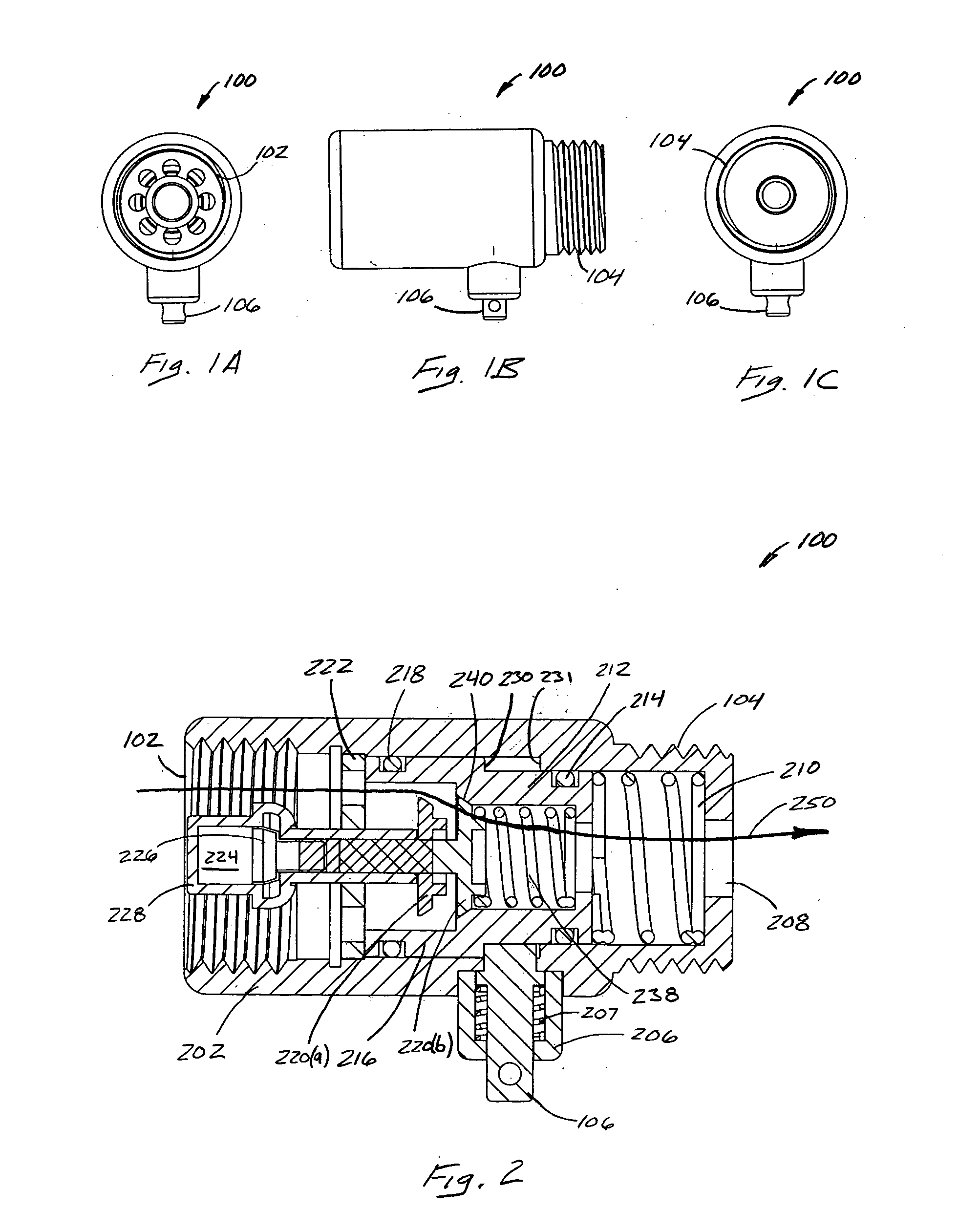
[0019]FIGS. 1A-1B show external overviews of a valve 100 in accordance with one embodiment of the present invention. More particularly, FIGS. 1A and 1C show respective end-on views of valve 100 shown in side view in FIG. 1B. In general, valve 100 includes, on the “in” end, a female threaded region 102, and on the opposite “out” end, a male threaded region 104. In addition, a release pin 106 or other such release mechanism is situated along the length of valve 100 to provide...


PUM


Abstract

A temperature-controlled valve allows the flow of water to be terminated automatically when the water flowing through the device reaches a specific temperature. The flow may thereafter be released automatically or manually, depending upon the application. The technology may be used in a variety of contexts, including, for example, stand-alone consumer or commercial valves, embedded applications, and custom-designed valves.

Description

CROSS-REFERENCE TO RELATED APPLICATIONS [0001] This application claims priority to provisional patent application Ser. No. 60 / 644,192, filed Jan. 14, 2005, the contents of which are hereby incorporated by reference.FIELD OF THE INVENTION [0002] The present invention generally relates to thermally-controlled valves. More particularly, the present invention relates to a device that allows the flow of water through a fixture (e.g., a shower head, a faucet, or other such fixture) to be automatically stopped automatically when the water reaches a particular temperature. BACKGROUND OF THE INVENTION [0003] It is often necessary, in both consumer and commercial contexts, to wait for a water source to reach a suitable temperature prior to use. For example, it is very common for an individual to turn on the hot water in a shower, or at a sink, then wait for an extended length of time until the water is at the correct temperature. In many cases, the individual simply walks away from the shower...

Claims


Application Information

Patent Timeline
Patent Type & Authority Applications(United States)
IPC IPC(8): G05D23/13G05D23/02F16K35/06
CPCF16K31/002G05D23/022Y10T137/7782
Inventor LOCKHART, JOHN
Owner AM CONSERVATION GRP
Why Eureka
Try Eureka