
Swabable fluid connectors and fluid connector pairs

a fluid connector and fluid connector technology, applied in the direction of hose connections, couplings, catheters, etc., can solve the problems of difficult to effectively clean with antiseptic solutions, large unaddressed circumstances, and difficult removal of such materials, so as to facilitate cleaning and reduce the likelihood of introduction of undesired materials

Inactive Publication Date: 2006-07-20
BAXTER ENGLEWOOD
View PDF63 Cites 51 Cited by
  • Summary
  • Abstract
  • Description
  • Claims
  • Application Information

AI Technical Summary

Benefits of technology

[0006] In view of the foregoing, a primary objective of the present invention is to provide an improved fluid connector that facilitates cleaning (e.g. disinfecting) prior to initial and any repeated interconnection(s) with another fluid connector, thereby reducing the likelihood of introduction of undesired material into a fluid stream passing between the connectors.
[0007] A further objective of the present invention is to provide an improved male connector or female connector that may be easily cleaned and readily employed or otherwise adapted for use with a wide variety of female connector designs or male connector designs, respectively.
[0008] An additional objective of the present invention is to provide an improved fluid connector that is not only readily cleanable but also easy-to-use.

Problems solved by technology

To date, however, a largely unaddressed circumstance of infectious material introduction to the bloodstream of a patient is when a male connector is used for multiple interconnections.
In turn, upon repeated usage of such male connectors, there are multiple opportunities for blood, nutritional fluids, and other fluids which include infectious materials to dwell in this space, and removal of such material and proper cleaning with antiseptic solutions is difficult to be effective.

Method used


Image

  • Swabable fluid connectors and fluid connector pairs
  • Swabable fluid connectors and fluid connector pairs
  • Swabable fluid connectors and fluid connector pairs

Examples


Embodiment Construction

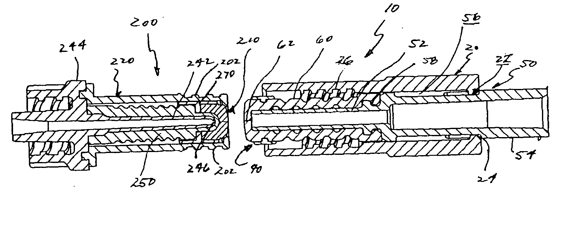
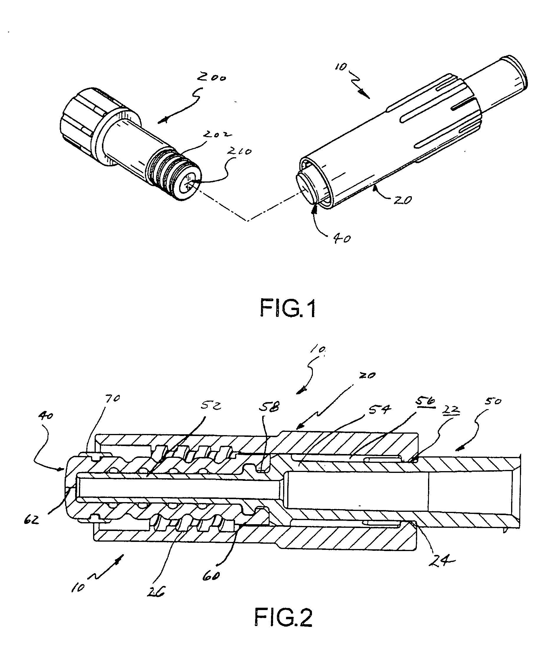
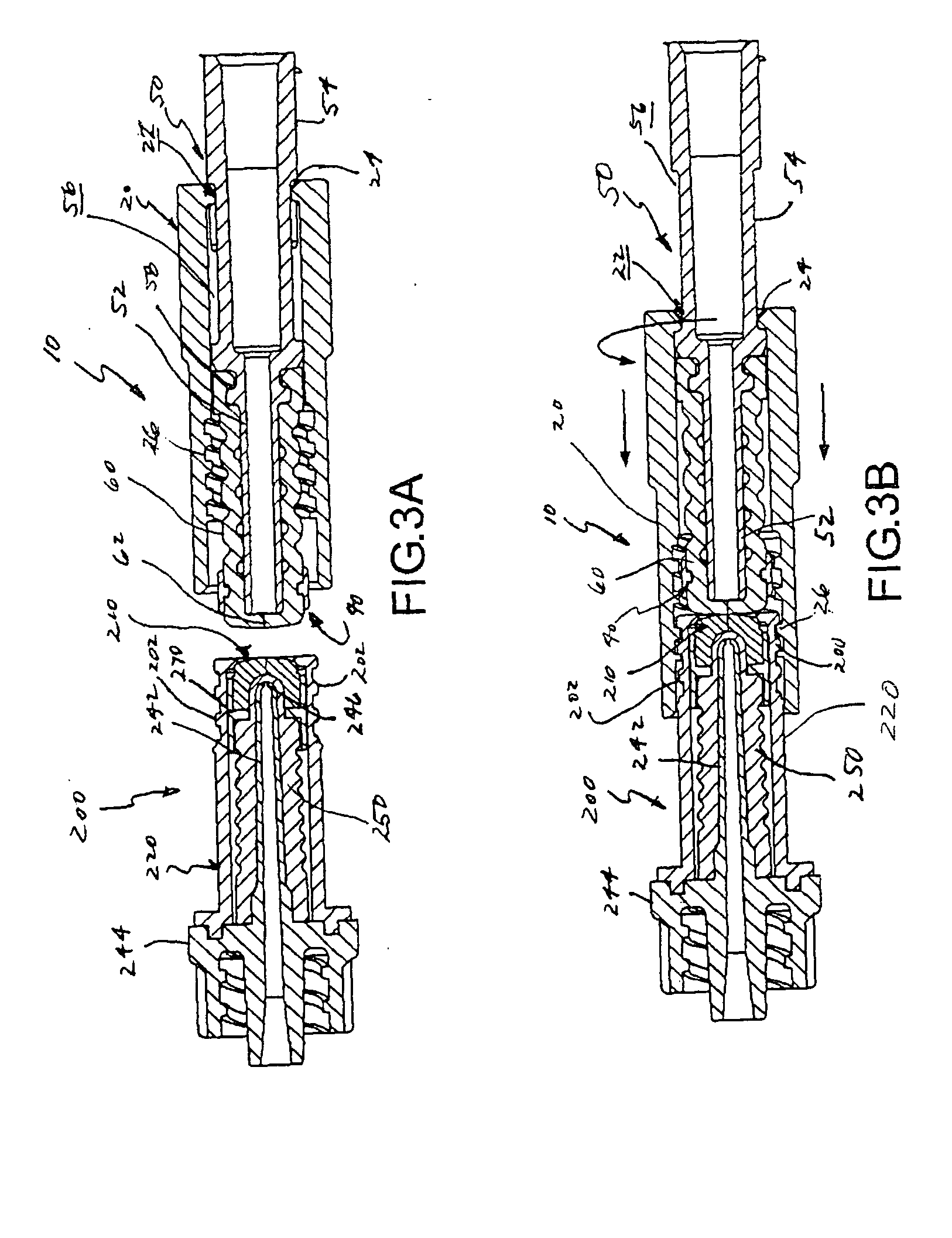
[0059]FIGS. 1 and 2 illustrate one embodiment of a fluid connector comprising the present invention. In this embodiment, a male connector 10 is provided for selective interconnection and fluid transfer with a female connector 200, e.g., a female connector as described in U.S. Pat. No. 6,113,068 hereby incorporated by reference in its entirety.

[0060] Before proceeding, it should be noted that fluid connectors of the present invention may include male and / or female connector implementations. Further, such implementations may be readily adapted for use with a wide variety of known fluid connector types, including in particular fluid connectors utilized in medical applications involving the transfer of medical liquids. In such various adaptations, fluid connectors of the present invention facilitate cleaning by a user (e.g. the application of a disinfectant) prior to interconnection with another fluid connector.

[0061] In the embodiment shown in FIG. 1, such capability may be provided ...


PUM


Abstract

A first fluid connector is provided for selective interconnection to and fluid transfer with a second fluid connector. The first connector comprises a fluid passageway, an internal member and an outer collar supportably disposed about the internal member for selective advancement and retraction relative thereto. At least a portion of the fluid passageway may extend through the internal member. The outer collar may be selectively retracted to facilitate cleaning of the internal member. In some embodiments, the outer collar and internal member may be disposed so that a distal portion of the internal member is substantially flush with or a distal portion of internal member projects beyond a distal end of the outer collar when the outer collar is in a retracted position relative thereto. To facilitate cleaning, a distal end or distal portion of the internal member may be substantially closed when the first and second connectors are disconnected. The second connector may be adapted to facilitate fluid interconnection with the first connector, and may also present a cleanable distal end when disconnected.

Description

FIELD OF THE INVENTION [0001] The present invention relates to the field of fluid connectors, and more particularly, to fluid connectors that may be selectively interconnected to and disconnected from other fluid connectors for selective fluid transfer therebetween, wherein a distal end of an internal member of at least a first fluid connector may be readily accessed for sterilization, e.g. via an antibacterial swabbing operation, prior to interconnection with a second fluid connector. The inventive features are particularly apt for use in medical liquid transfer applications, including in particular male and female connectors employed in the administration of medical liquids to patients via intravascular catheters. BACKGROUND OF THE INVENTION [0002] Numerous techniques are employed for the administration of “medical liquids” (e.g. liquid medications and flush solutions) to a patient. In particular, where repeated medication infusions are required, medical liquids are often administ...

Claims


Application Information

Patent Timeline
IPC IPC(8): F16L37/00
CPCA61M39/26F16L2201/44Y10S604/905A61M2039/267
Inventor BALDWIN, BRIAN EUGENESMITH, RANDALL WALLACEBALDWIN, GREGORY JOHN
Owner BAXTER ENGLEWOOD
Learn More