Image sensing apparatus and image processing method for use therein

a technology of image sensing apparatus and image processing method, which is applied in the direction of television system, color signal processing circuit, instruments, etc., can solve the problems of deterioration of contrast (tone or gradation), image sensing apparatus will inevitably suffer from increase in cost, and the advantage is likely to be unable to reflect in display, etc., to achieve high-quality display and improve contrast in picked-up images

Inactive Publication Date: 2006-07-20
SONY SEMICON SOLUTIONS CORP
View PDF2 Cites 47 Cited by
  • Summary
  • Abstract
  • Description
  • Claims
  • Application Information

AI Technical Summary

Benefits of technology

[0014] It is another object of the present invention to provide an image sensing apparatus and an image processing method which can improve contrast in a picked-up image, particularly contrast in a high luminance region of a picked-up image, and achieve high-quality display onto a display system or the like of the picked-up image.

Problems solved by technology

While this capability of ensuring a wider dynamic range is advantageous, an image signal is logarithmically compressed to cause a problem about deterioration in contrast (tone or gradation), particularly, in a logarithmic characteristic region.
Thus, even if a dynamic range is expanded in an image to be input to the display system, this advantage is likely to be unable to be reflected in display.
In this case, if such an image is handled (transmitted or stored) in a conventional manner, an image sensing apparatus will inevitably suffer from increase in cost.
However, the DR compression technique is designed for an image obtained through photoelectric conversion in a linear characteristic (linear characteristic image), and any compression technique for a linear / logarithmic image is not disclosed in the Non-Patent Publication 1.
This leads to increase in device cost.

Method used


Image

  • Image sensing apparatus and image processing method for use therein
  • Image sensing apparatus and image processing method for use therein
  • Image sensing apparatus and image processing method for use therein

Examples


first embodiment

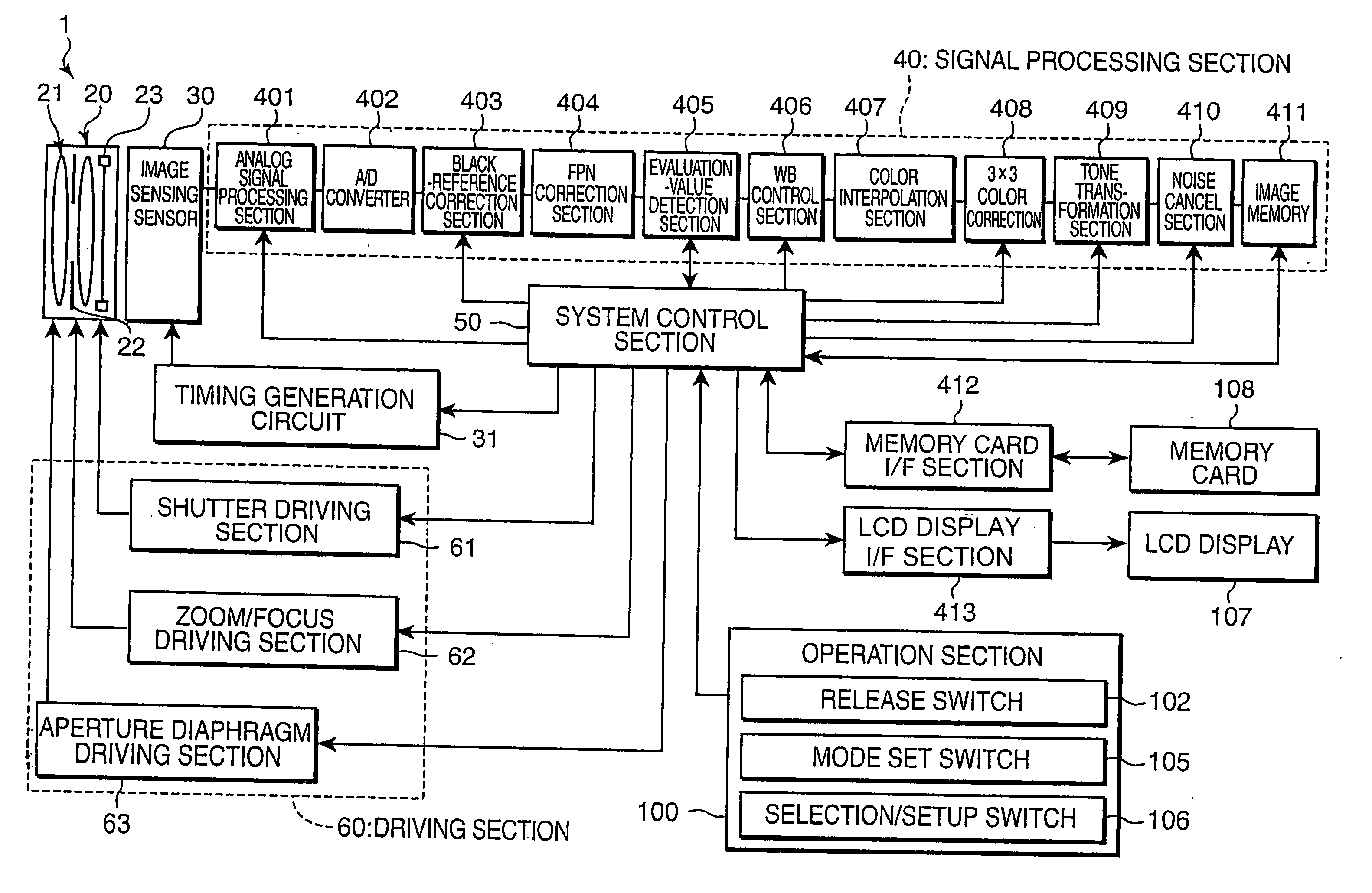
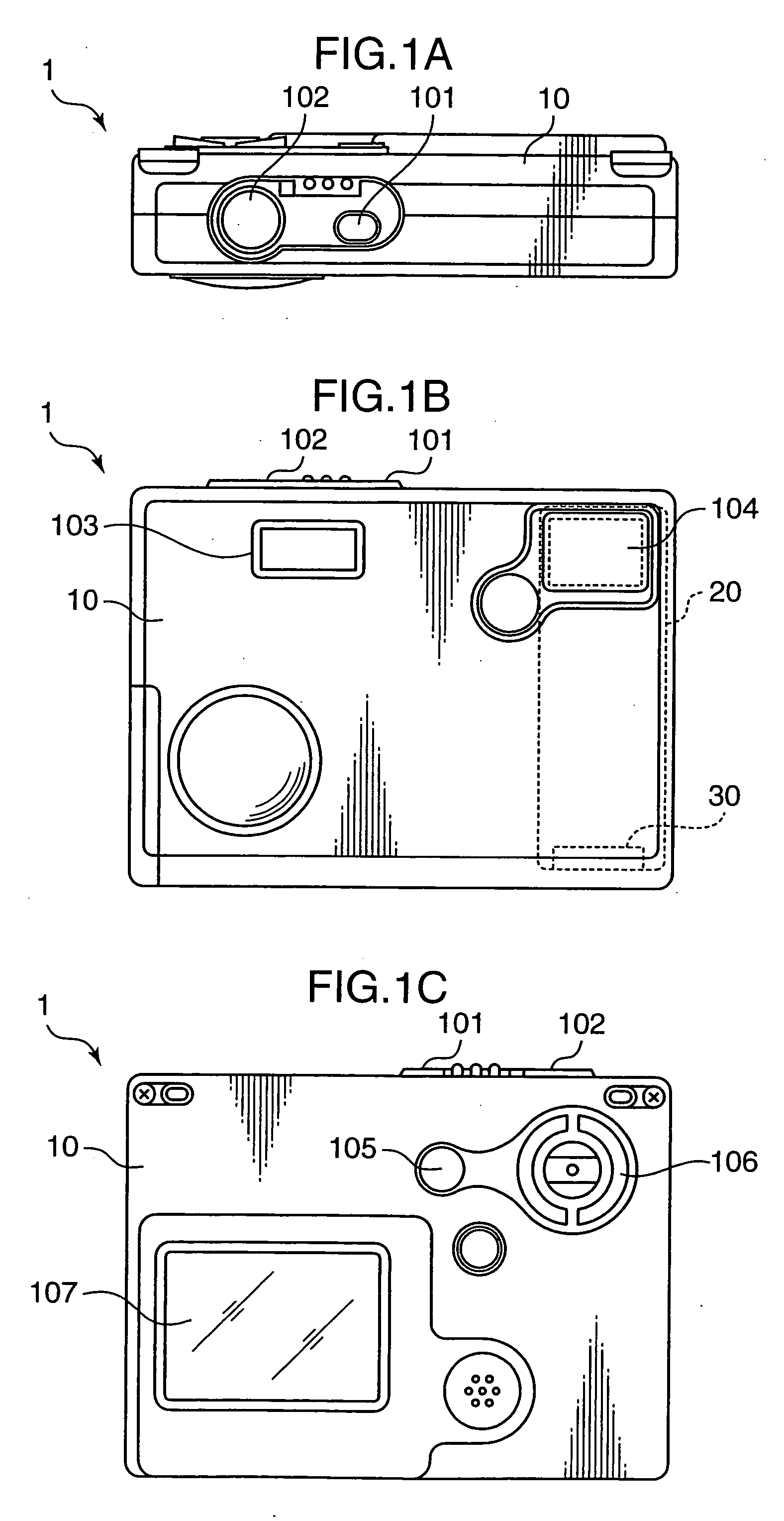
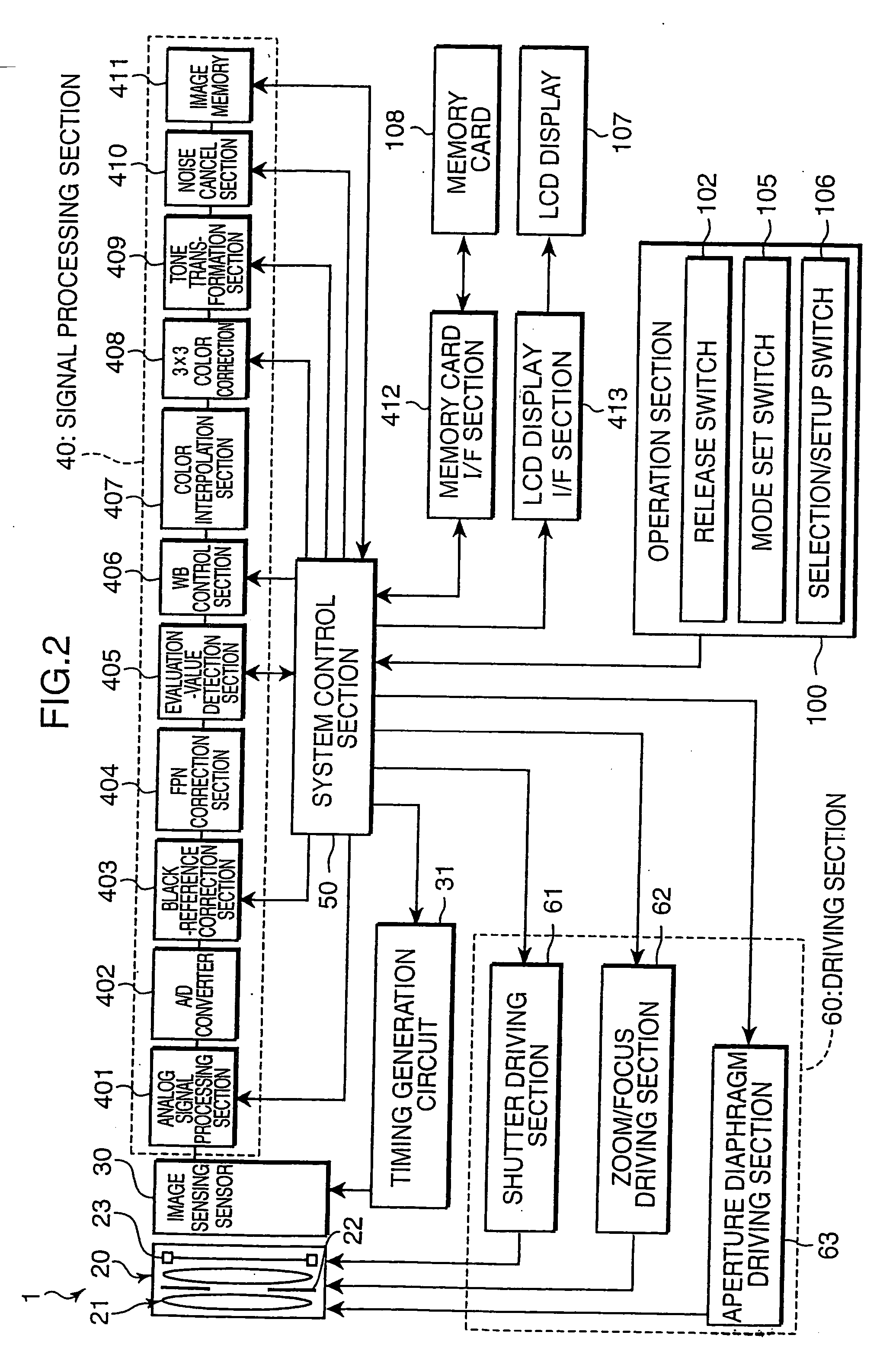
[0042]FIGS. 1A to 1C illustrate the appearance of a small-size digital camera 1 which is suitable as one application of an image sensing apparatus according to a first embodiment of the present invention, wherein FIGS. 1A, 1B and 1C are, respectively, a top view, a front view and a back view of the digital camera. This digital camera 1 comprises a camera main body 10 provided with various manual operation buttons, such as: a power switch 101 and a release switch 102 arranged in a top surface thereof; a flash generation section 103 and an image sensing lens window 104 arranged in a front surface thereof; and a mode set switch 105 and a selection / setup switch 106 arranged in a back surface thereof, and a LCD display 107 composed of a liquid-crystal monitor (LCD). The main body 10 has an inner space housing various main devices and a bent-type lens barrel 20.

[0043] The power switch 101 is a push-down type switch operable to turn on / off a power source of the camera 1. A user can repeat...

second embodiment

[0140]FIG. 16 is an explanatory block diagram of the function of a tone transformation section 409a of a digital camera 1a according to a second embodiment of the present invention. As shown in FIG. 16, in general, the tone transformation section 409a is different from the tone transformation section 409, in a point of comprising a circuit (processing block) for subjecting an image I2 to an illumination-component extraction processing and an illumination-component compression processing. The same component or element as that in the tone transformation section 409a is defined by the same reference numeral, and its description will be omitted, except that an illumination component extraction section 4092 for an image I1 is defined as a first illumination component extraction section 4092, and an illumination component compression section 4093 is defined as a first illumination component compression section 4093, only for simplifying the explanation.

[0141] The tone transformation sect...


PUM


Abstract

An illumination-component extractor (illumination component extraction section) extracts an illumination component Log from a picked-up image (original image) picked up an image sensor having a photoelectric conversion characteristic which comprises a linear characteristic region and a logarithmic characteristic region. A reflectance component determiner (subtraction section) extracts a reflectance component Log(R1). A compressor (illumination component compression section) subjects at least the illumination component Log of the logarithmic characteristic region to DR compression. Image production mean (image production section) produces a new image (synthetic image) based on the DR-compress illumination component and the reflectance component.

Description

[0001] This application is based on patent application No. 2004-377875 filed in Japan, the contents of which are hereby incorporated by references. BACKGROUND OF THE INVENTION [0002] 1. Field of the Invention [0003] The present invention relates to an image sensing apparatus equipped with an image sensor having a photoelectric conversion characteristic comprising a plurality of different characteristic regions, such as a photoelectric conversion characteristic which comprises a linear characteristic region where an electric signal is output therefrom while being transformed linearly relative to an incident light quantity and a logarithmic characteristic region where an electric signal is output therefrom while being transformed logarithmically relative to the incident light quantity, more specifically, a photoelectric conversion characteristic where a rate of change relative to the incident light quantity in a high luminance region is less than that in a low luminance region. In par...

Claims


Application Information

Patent Timeline
Patent Type & Authority Applications(United States)
IPC IPC(8): H04N5/228
CPCH04N3/155H04N5/2355H04N5/243H04N23/741H04N23/76H04N25/573
Inventor KATAGIRI, TETSUYA
Owner SONY SEMICON SOLUTIONS CORP
Why Eureka
Try Eureka