Electronic apparatus including connector terminal

Inactive Publication Date: 2006-07-20
ORION ELECTRIC CO LTD
View PDF3 Cites 14 Cited by
  • Summary
  • Abstract
  • Description
  • Claims
  • Application Information

AI Technical Summary

Benefits of technology

[0008] The present invention is made in view of the above described problem, and has an object to provide an electronic apparatus including a connector terminal which compactly houses a control board in a casing, and is capable of compactly drawing out an externally connecting cable drawn out of the rear surface of the casing without interfering with the other components on connection of the control board and an external apparatus, in a liquid crystal television receiving set or the like.
[0010] According to the above described construction, the connector terminal for connecting the cable of the external apparatus is mounted at an inclination angle of the inclined surface formed in the downward direction, and therefore, when the cable of the external apparatus is connected to the connector terminal, the cable is drawn out substantially vertically with respect to the inclination surface and drawn out in the state inclined in the downward direction, thus making it unnecessary to secure a useless space to draw out the cable to the rear side of the casing. While the control board is mounted substantially vertically in the casing, the connector terminal for connecting the cable of the external apparatus is mounted to be inclined with respect to the control board corresponding to the inclination angle of the inclination surface, and therefore, the control board is compactly housed in the casing, and it is not necessary to secure a wide space for mounting the control board in the casing.
[0012] According to the above described construction, the connector housing of the connecting connector is bent toward an outside, and therefore, the cable which is led out of the connecting connector is drawn out to a side of the cabinet, thus facilitating routing of the cable.

Problems solved by technology

According to the above described construction, the connector terminal for connecting the cable of the external apparatus is mounted at an inclination angle of the inclined surface formed in the downward direction, and therefore, when the cable of the external apparatus is connected to the connector terminal, the cable is drawn out substantially vertically with respect to the inclination surface and drawn out in the state inclined in the downward direction, thus making it unnecessary to secure a useless space to draw out the cable to the rear side of the casing.

Method used


Image

  • Electronic apparatus including connector terminal
  • Electronic apparatus including connector terminal
  • Electronic apparatus including connector terminal

Examples


embodiment 1

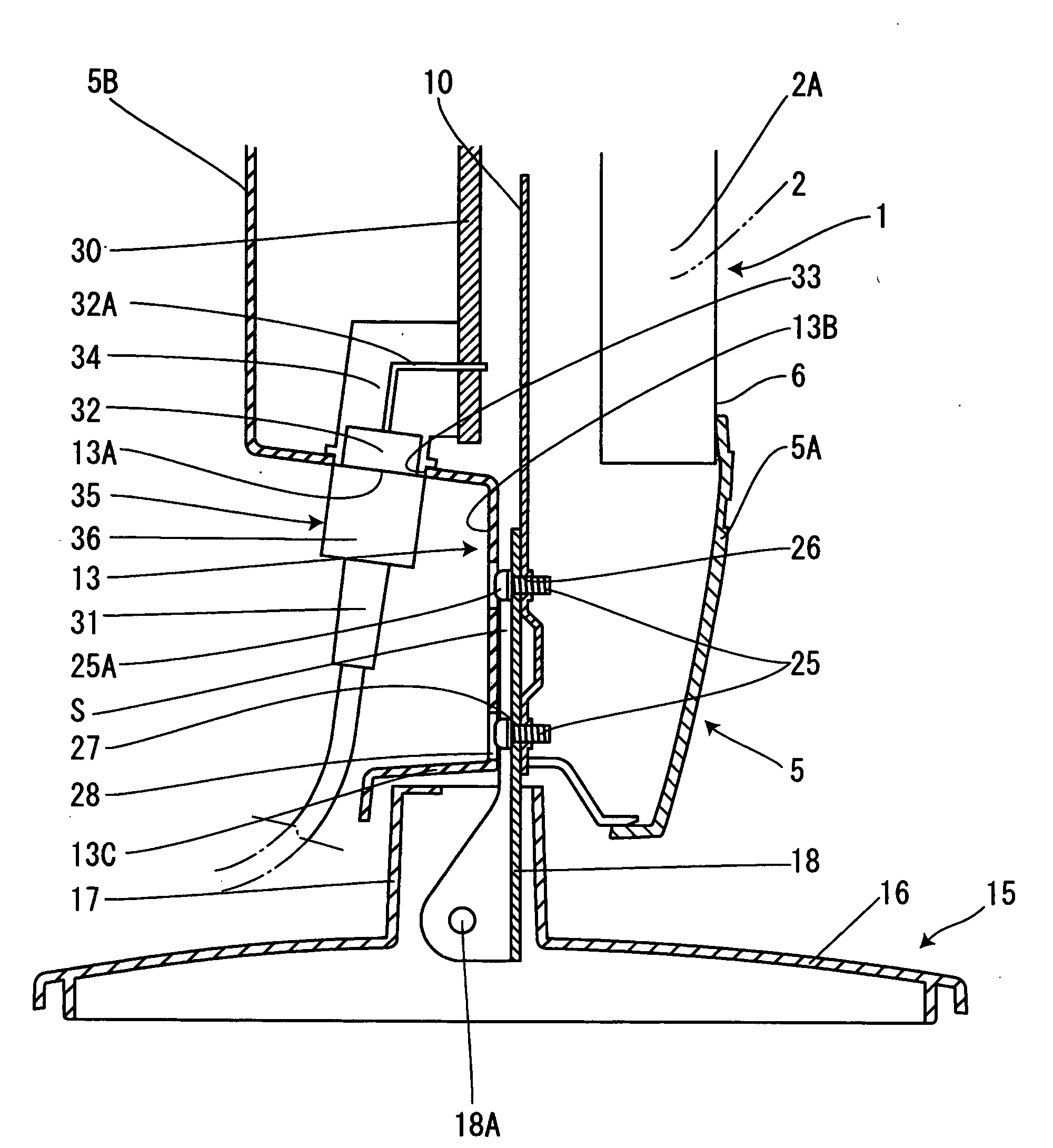
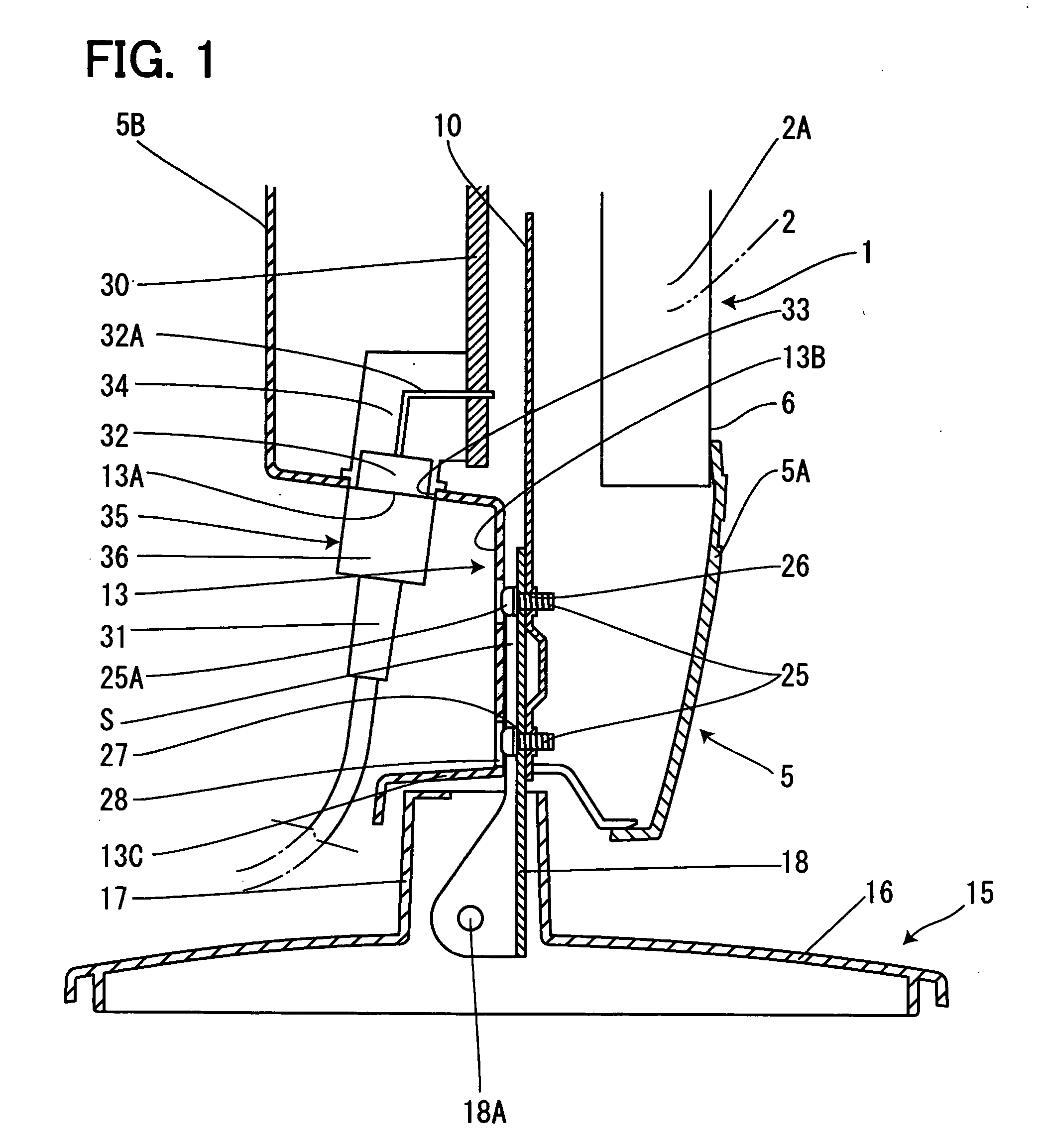
[0028] FIGS. 1 to 5 show embodiment 1 of the present invention, FIG. 1 is an enlarged sectional view showing a fixed state of a support bracket showing the embodiment 1 of the present invention, FIG. 2 is an enlarged sectional view showing a fixed state of a mounting bracket, FIG. 3 is a rear view showing a fixed state of the support bracket and the mounting bracket, FIG. 4 is a rear view of a cabinet, and FIG. 5 is a rear view of the cabinet in a state in which a back cabinet is removed. In the drawings, reference numeral 1 denotes a display unit, which is constructed by a liquid crystal panel 2 and a chassis 3 of metal for fixing the liquid crystal panel 2 to a cabinet which will be described later. The above described liquid crystal panel 2 includes a liquid crystal display element body not shown, and a panel fixing frame 2A of metal which covers an outer peripheral side from the rear surface of the liquid crystal display element body, and this panel fixing frame 2A is fixed by a...

embodiment 2

[0036]FIG. 6 shows embodiment 2 of the present invention, and the parts in common with the above described embodiment 1 are given the same reference numerals and characters, the explanation of the redundant parts is omitted, and only the different part will be described.

[0037] In the above described embodiment 1, the example in which the housing 36A of the connecting connector 35 in this embodiment is in the straight shape so that the cable 31 continues on the axis of the connecting connector 35, but in the embodiment 2, the connector housing 36 of the connecting connector 35 is bent toward an outside so as to guide the cable 31 to the side of the back cabinet 5B. By bending the connector housing 36A of the connecting connector 35 to the outside in this manner, the cable 31 which is connected to the connector terminal 32 via the connecting connector 35 is drawn out diagonally rearward from the back surface of the cabinet 5 by inclination of the inclined surface 13A, and is led out ...


PUM


Abstract

On connection of a control board and an external apparatus, an externally connecting cable which is drawn out from a rear surface of the casing can be drawn out without interfering with other components. A connector terminal 32 which connects the external apparatus is mounted to be inclined with respect to a control board 30 mounted substantially vertically in a cabinet 5, and is mounted along an inclined surface 13A formed in a downward direction in a stepped recessed part 13 of a back cabinet 5B. Thereby, a cable 31 which is connected to the connector terminal 32 does not interfere with a cover portion 13C of the stepped recessed part 13, which covers a support column part 17 of a stand 15.

Description

[0001] The present application is based on and claims priority of Japanese patent application No. 2005-010073 filed on Jan. 18, 2005, the entire contents of which are hereby incorporated by reference. BACKGROUND OF THE INVENTION [0002] 1. Field of the Invention [0003] The present invention relates to an electronic apparatus including a connector terminal, in which a connector terminal mounted on a control board is fitted to a rear surface of a casing so as to connect an external cable via the connector terminal. [0004] 2. Description of the Related Art [0005] An electronic apparatus such as a television receiving set generally includes various kinds of input and output terminals, and connects an external apparatus to these input and output terminals to input or output signals, and on connection with the external apparatus, a connector terminal of the input and output terminal is conventionally mounted on a control board which is housed in a casing of a television receiving set or th...

Claims


Application Information

Patent Timeline
IPC IPC(8): H05K1/00
CPCH05K1/18H05K2201/10189H01R12/712H05K2201/10484H05K2201/10446
Inventor NISHIDA, KAZUFUMIAOYAMA, SHIN'ICHI
Owner ORION ELECTRIC CO LTD
Why Eureka
Try Eureka