

Stacking type tray and tray developing mechanism and stacking type tray developing system
a technology of developing mechanism and developing system, which is applied in the direction of packaging goods, instruments, transportation and packaging, etc., can solve the problems of increasing the price, notably the mass capacitance of the storage device for storing information, and the inability to utilize conventional production facilities
- Summary
- Abstract
- Description
- Claims
- Application Information
AI Technical Summary
Benefits of technology
Problems solved by technology
Method used
Image

Examples
Embodiment Construction
[0022]Next, best modes for carrying out the invention will be described in details by referring to specific examples.
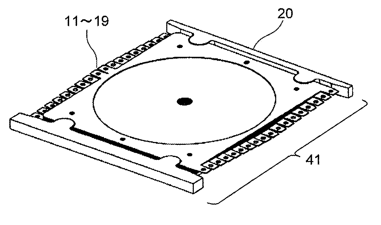
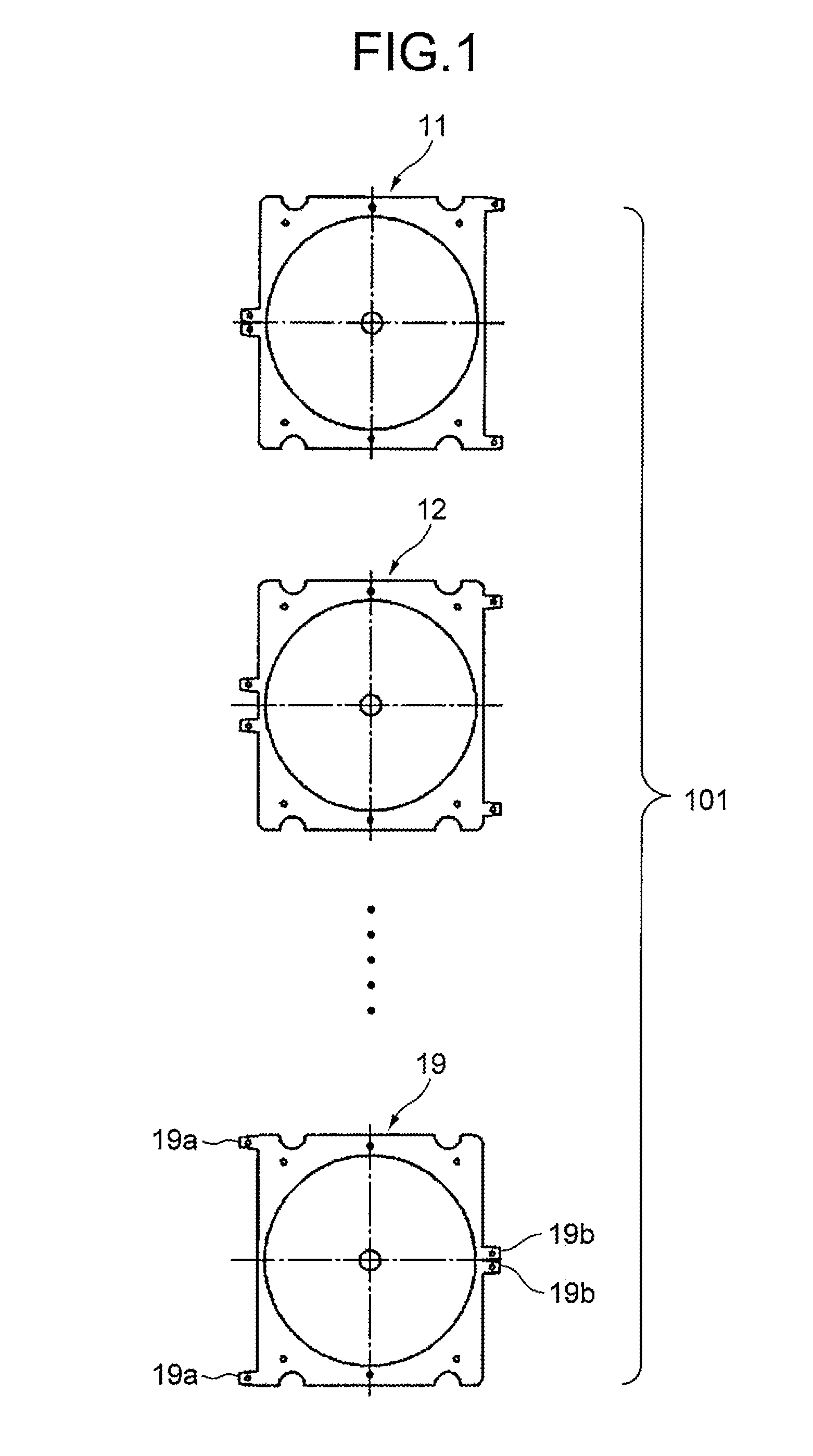
[0023]FIG. 1 is a plan view showing a schematic structure of each tray by referring to a case where a stacking type tray 101 is formed by stacking nine pieces of trays for loading optical discs 100 as a type of disc-type recording media in the thickness direction.
[0024]In this exemplary embodiment, the tray located at the uppermost layer in a stacked state is called a first tray 11, the tray thereunder is called a second tray 12, and the trays thereunder are also called as a third tray 13, a fourth tray 14, - - - , and a ninth tray 19 in the same manner. In FIG. 1, illustrations of the trays from the third tray 13 to the eighth tray 18 are omitted.
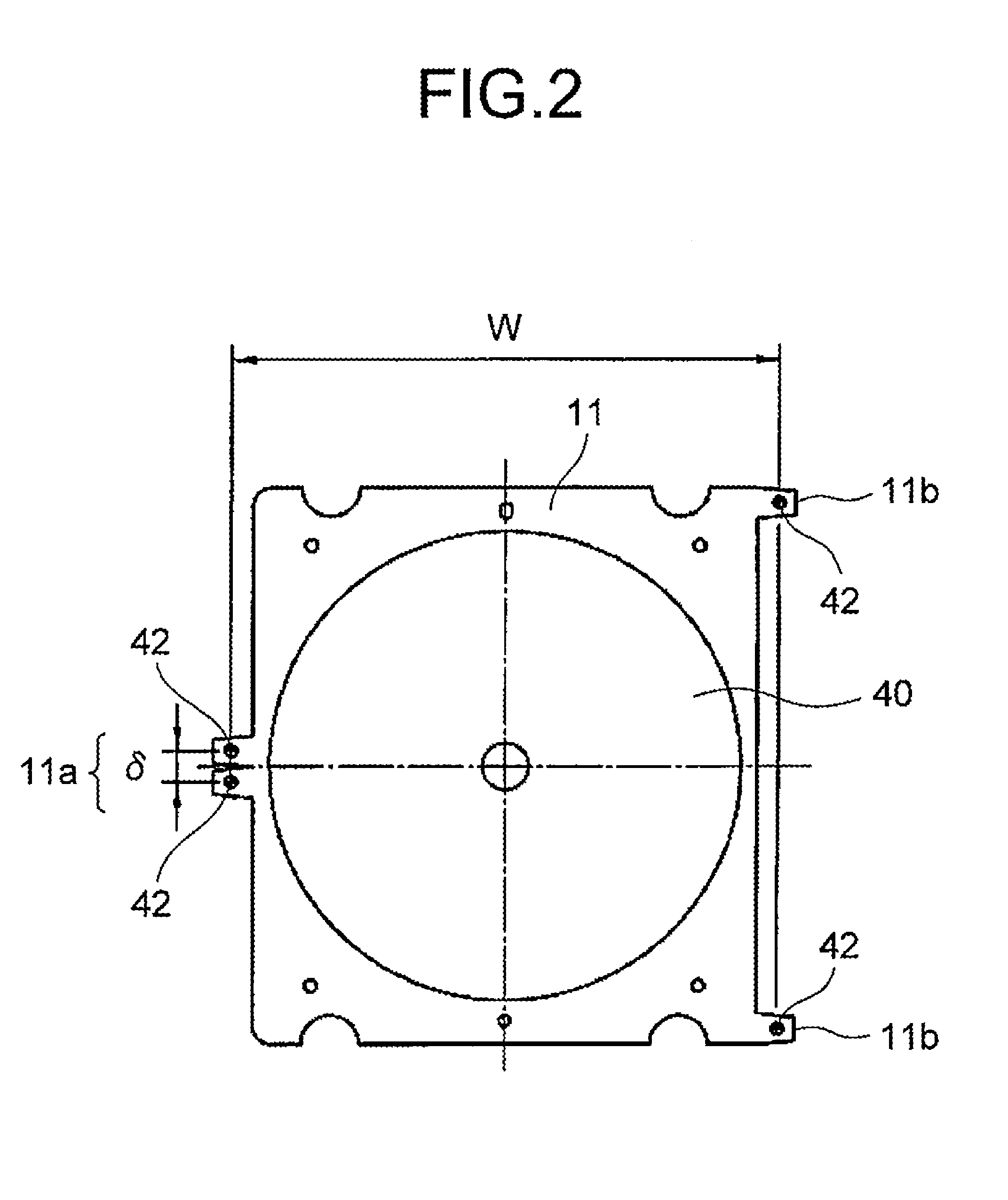
[0025]The basic structures of the first tray 11 to the ninth tray 19 are the same, so that the structures in common to the first tray 11 to the ninth tray 19 will be described herein by referring to the case of the first tra...
PUM
| Property | Measurement | Unit |
|---|---|---|
| thickness | aaaaa | aaaaa |
| distance | aaaaa | aaaaa |
| length | aaaaa | aaaaa |
Abstract
Description
Claims
Application Information