UV irradiation device and inkjet printer

Inactive Publication Date: 2012-11-14
GS YUASA INT LTD
View PDF10 Cites 4 Cited by
  • Summary
  • Abstract
  • Description
  • Claims
  • Application Information

AI Technical Summary

Problems solved by technology

[0012] However, the cooling air generated by the cooling air generating mechanism not only cools the ultraviolet lamp, but also cools other adjacent components. Therefore, if it is only the ultraviolet lamp, it is not preferable to change the cooling capacity arbitrarily. There are also restrictions on the adjustment

Method used


Image

  • UV irradiation device and inkjet printer
  • UV irradiation device and inkjet printer
  • UV irradiation device and inkjet printer

Examples


Embodiment Construction

[0076] Hereinafter, embodiment of the ultraviolet irradiation apparatus of this invention is demonstrated based on drawing.

[0077] The ultraviolet irradiation device UR of this embodiment is mounted on the print head of the inkjet printing device for business use, and when the print head is scanned to form an image, it moves together with the print head, and the UV ink of the formed image is irradiated with ultraviolet rays Make it harden instantly.

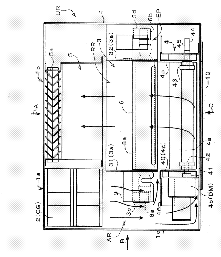
[0078] figure 1 It shows the internal structure in the state which removed the cover of the front side of the apparatus casing of the ultraviolet irradiation apparatus. The ultraviolet irradiation device UR has a rectangular parallelepiped-shaped device housing 1, and is mainly composed of a blower unit 2, a lamp unit 3, a shutter unit 4, and an exhaust duct 5. These units are connected to each other or fixed in the device housing 1 by fixing members not shown in the figure.

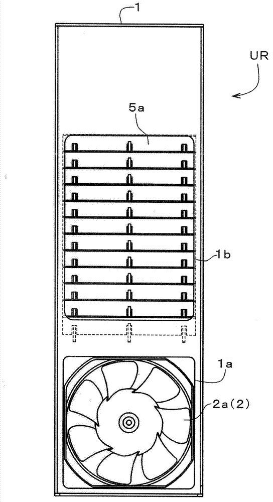
[0079] image 3 expressed in figure 1 The appe...


PUM


Abstract

In order to achieve cooling according to the usage state of an ultraviolet lamp, using a simple configuration, a UV irradiation device is provided with: a UV lamp (6); a cooling air generating means (CG) that generates cooling air that flows inside a device housing (1) that houses the UV lamp (6); and a shutter (4a) that is switched between an open position that permits the emission of radiation from the UV lamp (6) to the exterior of the device housing (1) and a closed position that inhibits the emission of radiation from the UV lamp to the exterior. The UV lamp (6) is set in such a manner that the UV radiation output when the shutter (4a) is in a closed position is smaller than when the UV radiation output is in the open position, and the shutter (4a) is positioned partway along the path of the cooling air that is generated by the cooling air generating means (CG), and is constituted so as to shut off the passage of the cooling air that reaches the UV lamp (6) when in a closed position, and to open the passage of cooling air that reaches the UV lamp (6) when in an open position.

Description

technical field [0001] The present invention relates to an ultraviolet radiation device and an inkjet printing device provided with the ultraviolet radiation device. The ultraviolet radiation device comprises: an ultraviolet lamp; cooling wind; and a shutter operated to switch between an open posture that allows the emitted ultraviolet rays of the ultraviolet lamp to be emitted to the outside of the device housing, and an open posture that prevents the ultraviolet lamp from being emitted. It emits ultraviolet rays to the outside. Background technique [0002] Such an ultraviolet irradiation device is used in various applications such as a processing step of semiconductor elements and a cleaning step of various components. [0003] Since a high voltage is applied to an ultraviolet lamp arranged in an ultraviolet irradiation device, the temperature of the ultraviolet lamp rises during the light emitting operation. Therefore, a cooling mechanism for cooling the ultraviolet lam...

Claims


Application Information

Patent Timeline
Patent Type & Authority Applications(China)
IPC IPC(8): B41J2/01B01J19/12B05C9/12G03F7/20H01J61/52
CPCB41J11/002B41J11/00214B41J11/0022B41J11/00218B41J2/01
Inventor 角波雅之
Owner GS YUASA INT LTD
Why Eureka
Try Eureka