
Outboard motor

Inactive Publication Date: 2009-08-13
YAMAHA MOTOR CO LTD
View PDF6 Cites 5 Cited by
  • Summary
  • Abstract
  • Description
  • Claims
  • Application Information

AI Technical Summary

Benefits of technology

[0006]In order to overcome the problems described above, preferred embodiments of the present invention provide an outboard motor capable of ensuring a stable pump discharge amount without incurring increases in oil pump size and an oil amount.
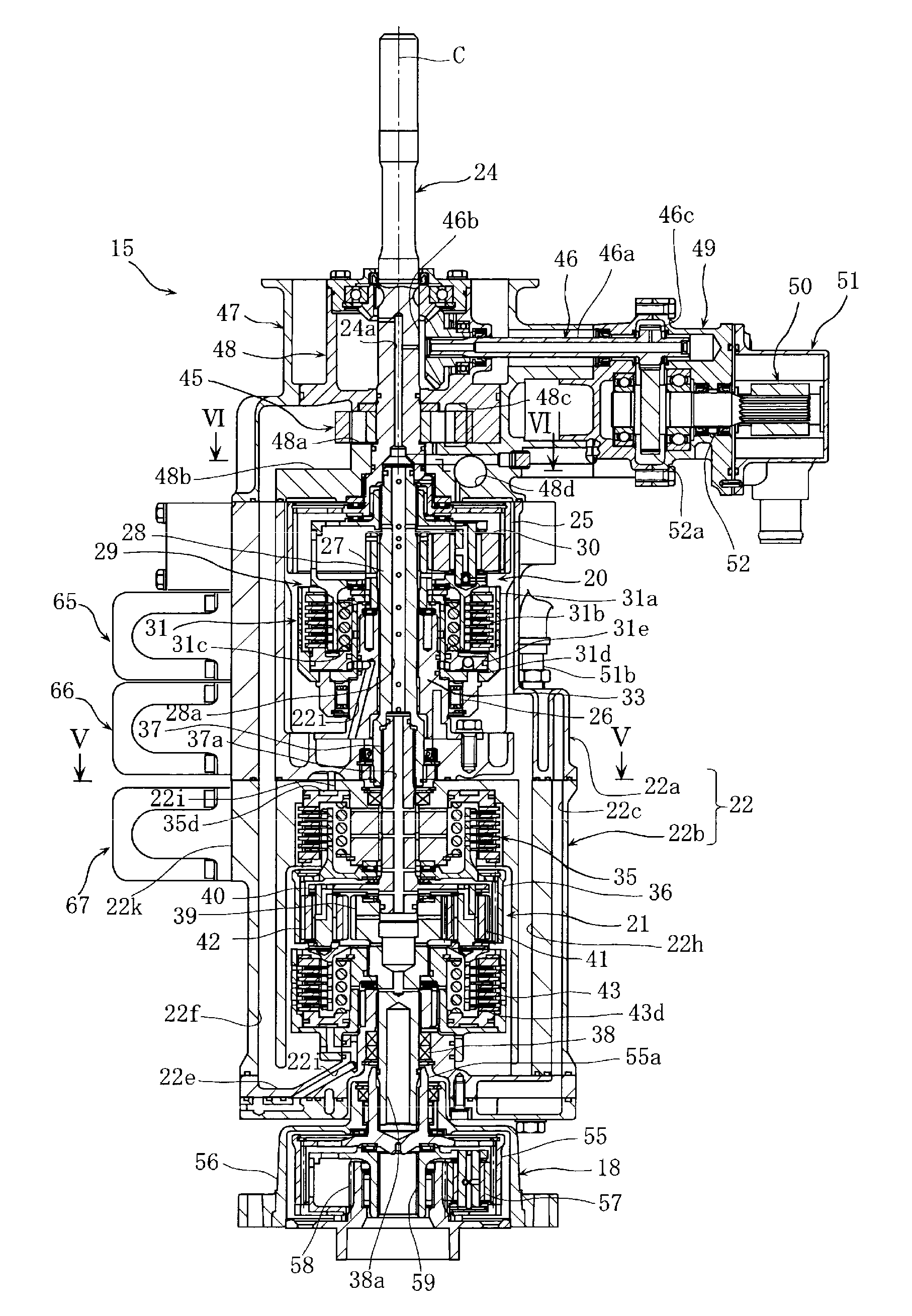
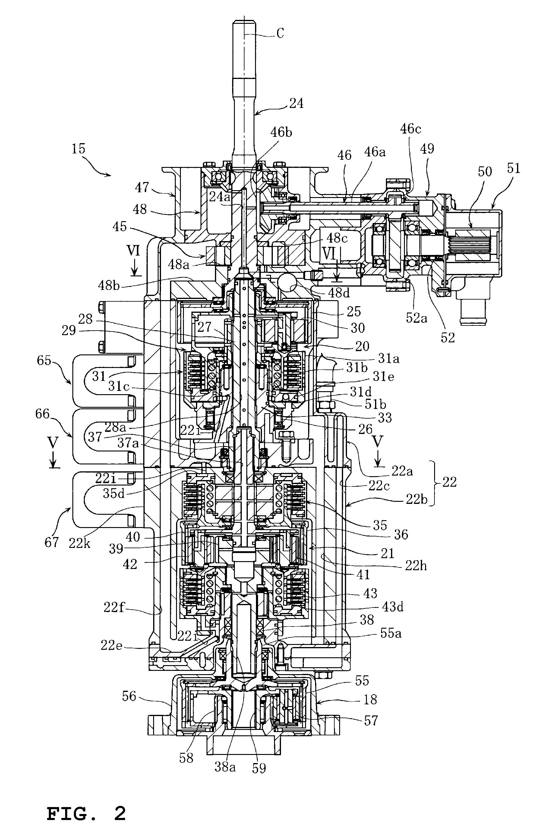
[0011]In the outboard motor in accordance with the first preferred embodiment of the present invention, the oil pump is disposed on the power transmitting shaft rotating together with the engine thus preventing fluctuation of the ratio between the rotational speed of the oil pump and the engine speed. This facilitates setting of the oil amount corresponding to each engine speed and stable securing of a required pump discharge amount.
[0012]In the second preferred embodiment of the present invention, the driving force acquisition mechanism arranged to acquire driving force is provided on the power transmitting shaft. Therefore, engine power can be acquired from the power transmitting shaft separately from the oil pump, and a driving force proportional to the rotational speed of the engine can be acquired. As a result, an acquired driving force can be used for a wider range of purposes. For example, it is possible to secure a sufficient amount of coolant supply to the engine and so forth in the case that a coolant pump is connected to the driving force acquisition mechanism.
[0013]The second housing in which the oil pump is housed is connected to the first housing connected to the engine inside the first housing. The third housing in which the driving force acquisition mechanism is housed is connected to the first housing outside the first housing. Therefore, two mechanisms of the oil pump and the driving force acquisition mechanism can be compactly housed, thus facilitating assembly.
[0014]In the third preferred embodiment of the present invention, the relief passage is arranged in the second housing which houses the oil pump, and the relief valve is interposed in the relief passage. Therefore, the relief valve can be disposed in the second housing utilizing an open space, thus achieving a downsizing of the whole power transmitting portion.
[0015]In the fourth preferred embodiment of the present invention, the oil discharge passage and the oil drawing passage are provided on one side in the watercraft width direction of the straight line extending in the traveling direction through the power transmitting shaft. Therefore, the oil drawing passage and the oil discharge passage can be disposed on the front side and the rear side, respectively, in a rotational direction of the oil pump. Accordingly, an oil line configuration can be simplified. Oil is directly drawn from a section in which oil collects, thereby allowing for a reduction in the length of a drawing line to the oil pump. Consequently, this allows for a significant reduction in the total amount of oil and in the size of the oil pump, thus achieving a cost savings.

Problems solved by technology

However, if the oil pump is disposed adjacent to the oil reservoir, rotation of the engine that is reduced by the transmission mechanism is transmitted to the oil pump, thus causing a fluctuation of the rotational speed of the oil pump.
This results in an undesirable increase in the cost and weight of the outboard motor.

Method used


Image

  • Outboard motor
  • Outboard motor
  • Outboard motor

Examples


Embodiment Construction

[0027]Preferred embodiments of the present invention will be described hereinafter with reference to attached drawings.

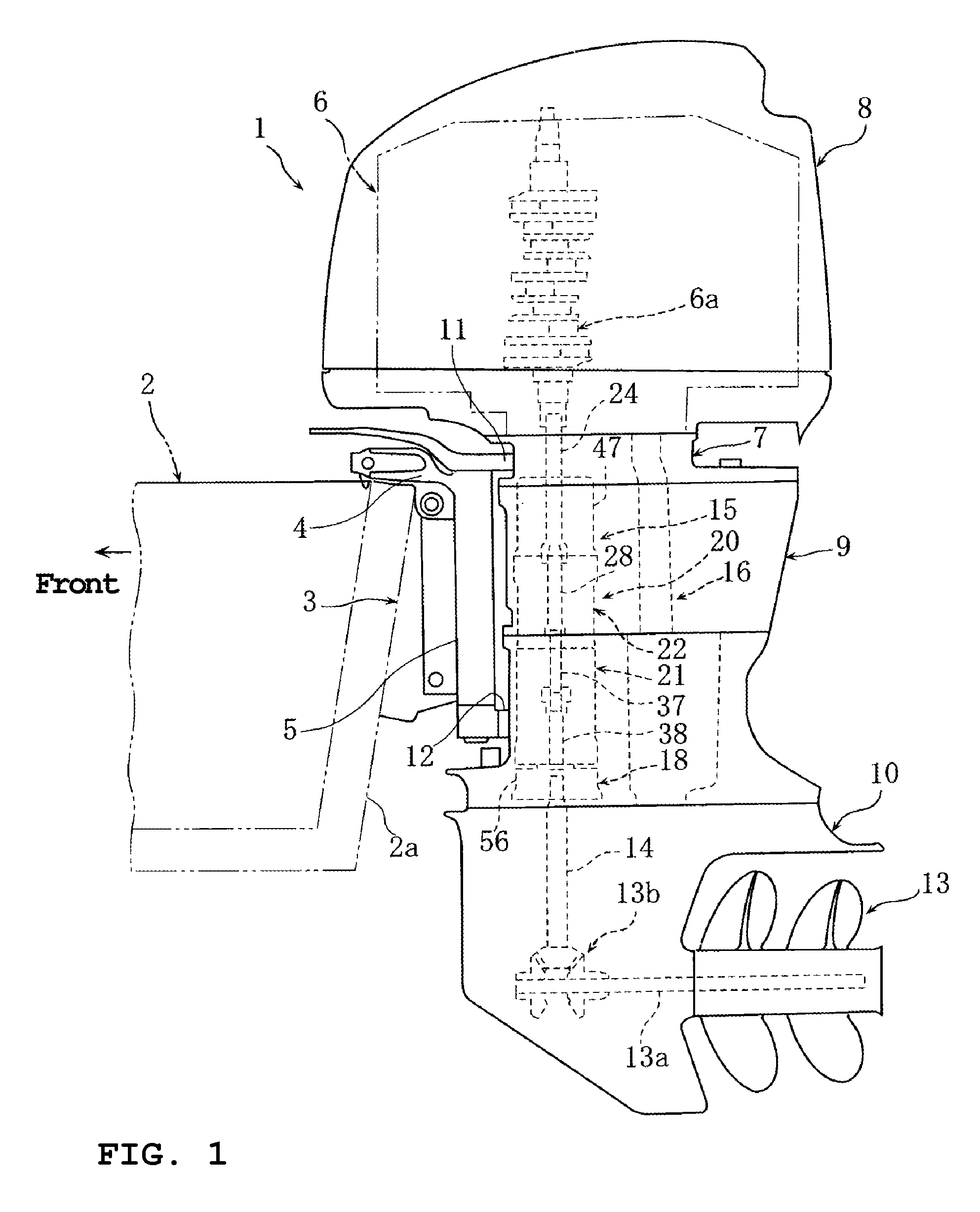
[0028]FIGS. 1 through 10 are drawings for describing an outboard motor in accordance with preferred embodiments of the present invention. Front, rear, right, and left in descriptions of the preferred embodiments denote front, rear, right, and left in the view as seen from the rear of a watercraft unless otherwise specified.

[0029]In the figures, reference numeral 1 denotes an outboard motor installed in a stern 2a of a hull 2. The outboard motor 1 is supported swingably in the vertical direction by a clamp bracket 3 fixed to the hull 2 via a swivel arm 4 and supported to be steerable to the right and left via a pivot portion 5.

[0030]The outboard motor 1 has an engine 6 arranged to generate power, an exhaust guide 7, a cowling 8, an upper case 9, and a lower case 10.

[0031]The engine 6 includes a vertically oriented crankshaft 6a disposed in a generally vertical direct...


PUM


Abstract

A power transmitting portion of an outboard motor has a power transmitting shaft connected to an output shaft of an engine to rotate together therewith, an oil pump disposed on the power transmitting shaft, and a driving force acquisition mechanism arranged to acquire driving force from the power transmitting shaft. The power transmitting portion is able to provide an outboard motor capable of ensuring a pump discharge amount without incurring an increase in the pump size and the oil amount.

Description

BACKGROUND OF THE INVENTION[0001]1. Field of the Invention[0002]The present invention relates to an outboard motor including a transmission device arranged to change the speed of rotation of an engine and to transmit the rotation to a propeller.[0003]2. Description of the Related Art[0004]An outboard motor including a hydraulic clutch type transmission mechanism which shifts the speed of rotation of an engine between high speed and low speed positions and transmits the rotation to a propeller, an oil pump supplying hydraulic pressure to the hydraulic clutch type transmission mechanism, and a hydraulic pressure control valve controlling hydraulic pressure supplied to the hydraulic clutch type transmission mechanism is known in the art. See, for example, WO 2007-007707 A1.[0005]There are cases in which increasing the oil drawing rate of an oil pump is desired when the oil pump is disposed as close to an oil reservoir as possible in outboard motors including the hydraulic clutch type t...

Claims


Application Information

Patent Timeline
IPC IPC(8): B63H21/38B63H20/14
CPCB63B2770/00B63H20/14F16H3/60F16H3/54F02B61/045B63H20/002B63H2005/106
Inventor OKABE, YOSHIHIKO
Owner YAMAHA MOTOR CO LTD
Learn More