System and method of dewatering dredge spoils using sloping drain barge

a technology of dredging spoils and drain barges, which is applied in the direction of machines/engines, foundation engineering, sedimentation settling tanks, etc., can solve the problems of what to do with spoils and water being brought up as an unavoidable consequen

Inactive Publication Date: 2006-07-27
GEN CONSTR
View PDF46 Cites 11 Cited by
  • Summary
  • Abstract
  • Description
  • Claims
  • Application Information

AI Technical Summary

Problems solved by technology

Whatever the purpose or method, dredging operations inherently create the problem of what to do with the “spoils” created as mud, sand, sediment and other materials are removed from the bottom and brought to the surface.
The water is brought up as an unavoidable consequence inherent in the dredging operation itself.

Method used


Image

  • System and method of dewatering dredge spoils using sloping drain barge
  • System and method of dewatering dredge spoils using sloping drain barge
  • System and method of dewatering dredge spoils using sloping drain barge

Examples


Embodiment Construction

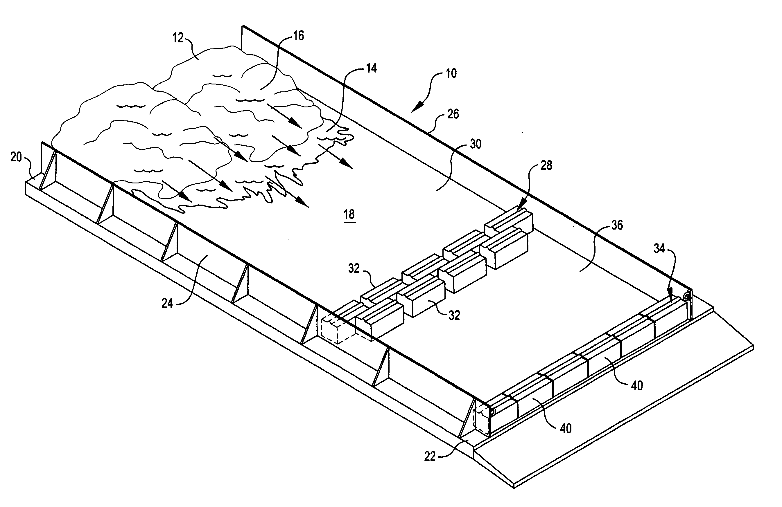
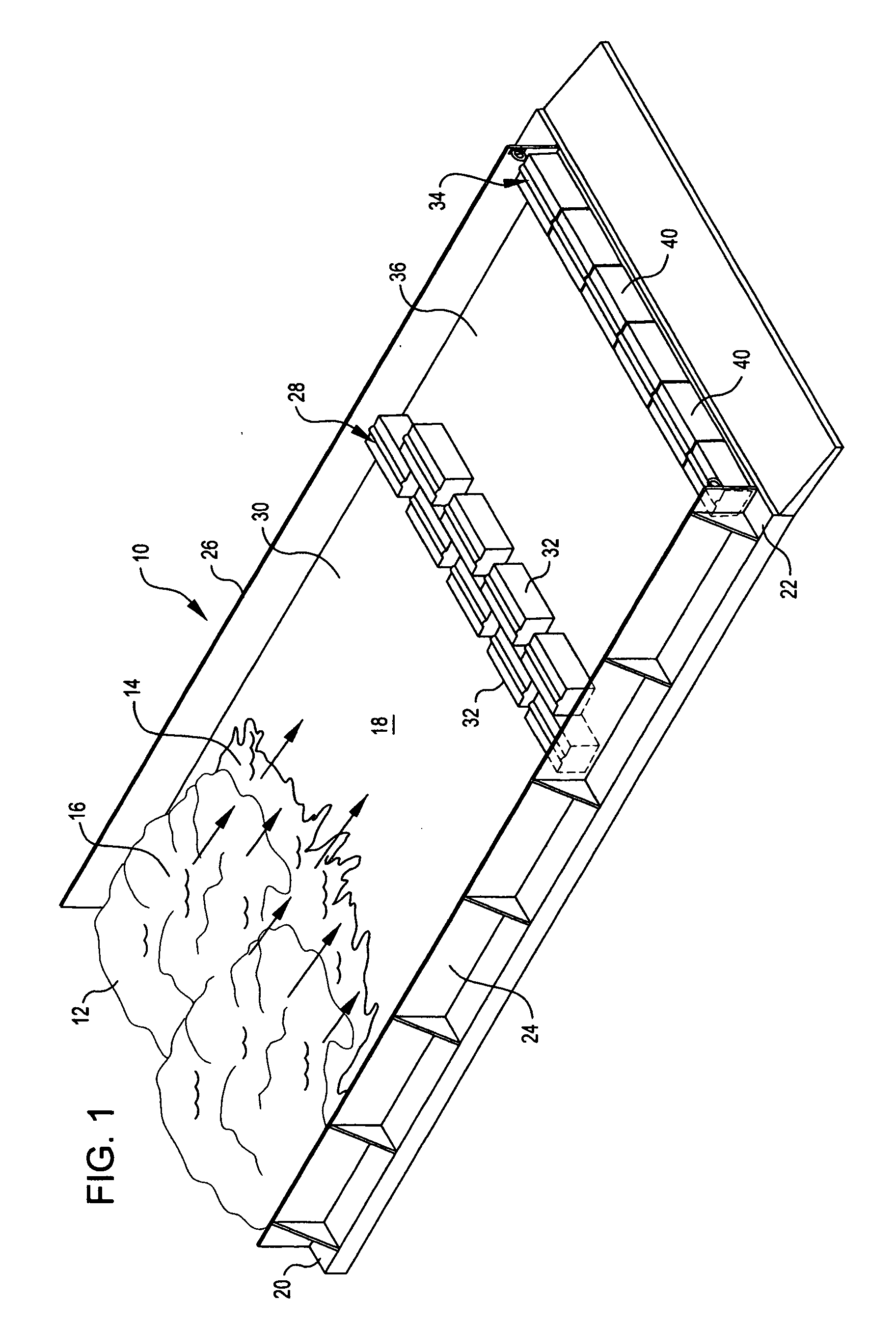
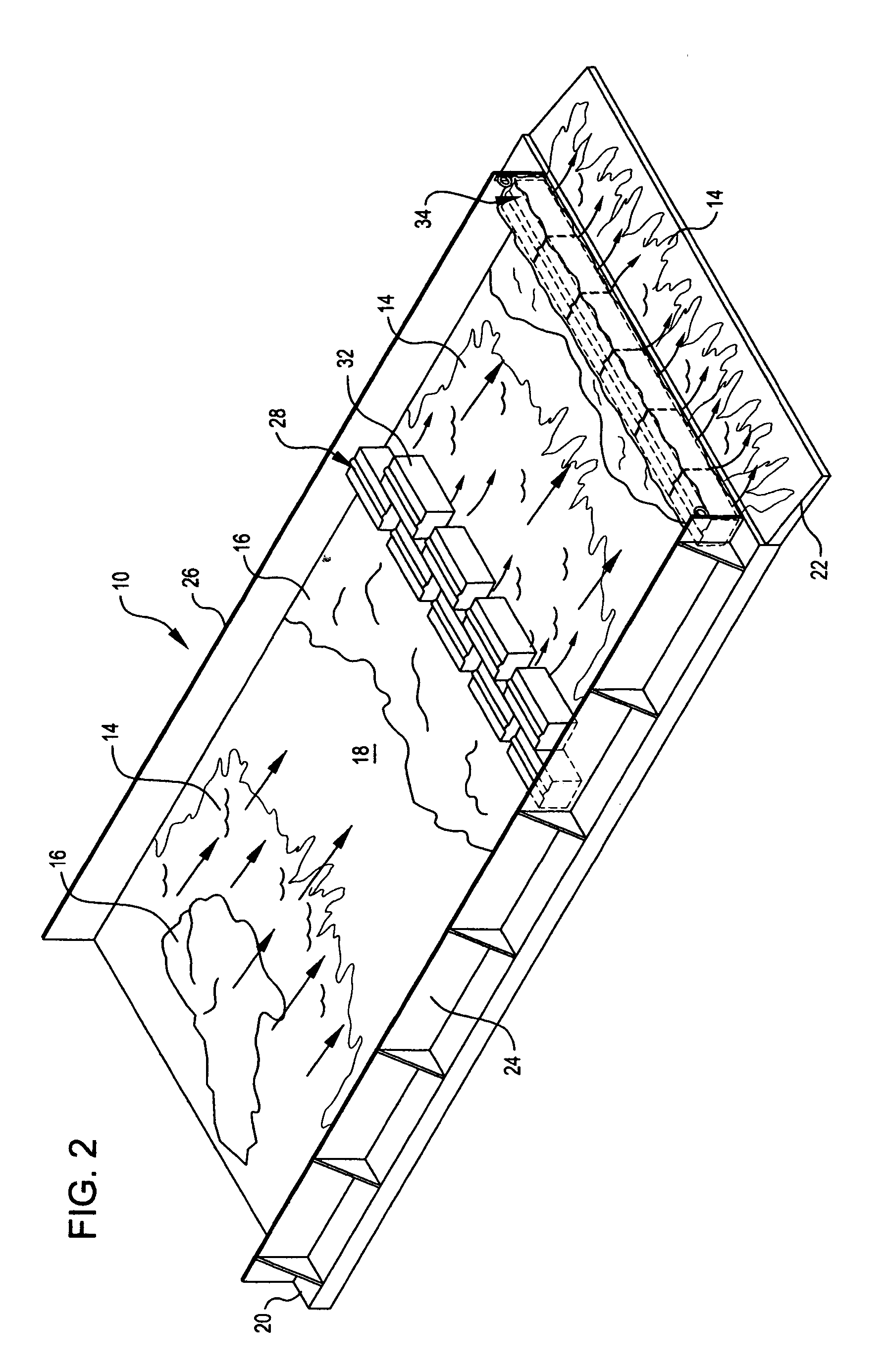
[0016] Referring to the drawings and in particular to FIG. 1, an apparatus 10 for dewatering dredge spoils 12 is illustrated. As used herein, the term “dredge spoils” will be understood to mean materials that are removed from a waterway during dredging operations. Regardless of the particular waterway and bottom involved, and regardless of the purpose for which the dredging operation is being carried out, the dredge spoils will be understood to contain both a liquid component 14, such as water, and a solid component 16, such as mud, silt or sand, suspended in the liquid. The general function of the dewatering apparatus 10 and method shown and described herein, is substantially to separate the solid components 16 of the dredge spoils from the liquid component 14. The liquid component 14 can then be returned to the waterway while the solid components 16 are collected for disposal elsewhere. It will be understood that these are relative terms, and that in practice, the complete separat...


PUM

PropertyMeasurementUnit
movementaaaaaaaaaa
depthaaaaaaaaaa
distancesaaaaaaaaaa

Abstract

An apparatus for dewatering dredge spoils includes a floating barge having a planar upper surface or deck. One end of the barge, such as the stem, is partially flooded or otherwise ballasted so that the deck slopes downwardly from the bow toward the stem. Dredge spoils removed from a waterway are deposited onto the bow where they flow down toward the stem. A plurality of concrete blocks on the deck form an attenuator that, in turn, defines one or more settling ponds on the surface of the barge. A weir across the stem of the barge forms an additional settling pond at the rear of the barge. Solids suspended in the water removed from the waterway settle out onto the deck when the dredge spoils are deposited onto the bow. Remaining solids suspended in the water deposit onto the deck as the water flows through the settling ponds. The relatively clear water that remains then flows back into the waterway off the stem of the sloped barge after passing through the settling ponds. Because the apparatus and method use materials and equipment, such as the barge and blocks, that are already likely to be on hand, the method and apparatus are particularly economical and easy to implement.

Description

FIELD OF THE INVENTION [0001] This invention relates generally to dredging equipment and more particularly to devices and methods for separating and collecting the solid components of dredge spoils. BACKGROUND OF THE INVENTION [0002] Dredging is a common operation wherein bottom materials, such as mud, sand and sediment, are removed from a waterway. Dredging can be performed for a number of reasons, such as increasing the depth of a harbor, channel or river to permit the safe passage of deep-draft vessels. Dredging can also be performed to permit the recovery of minerals or other valuable raw materials from areas that are underwater. In addition, dredging can be used to remove contaminated sediments from polluted harbors and rivers as part of a remedial clean-up operation. [0003] Typically, dredging is performed by means of a crane operated bucket that is repeatedly raised and lowered into the water to scoop up bottom materials and bring them to the surface for removal. Other forms ...

Claims


Application Information

Patent Timeline
Patent Type & Authority Applications(United States)
IPC IPC(8): E02F3/00
CPCB01D21/00B01D21/0015B01D21/0042B01D21/02B01D21/2438B01D21/245B63B35/00E02F7/06B01D21/0039
Inventor LANGDON, BRIAN BERNARDPRESTON, KENNETH ANTHONYCOULTAS, THOMAS EDWARD
Owner GEN CONSTR
Why Eureka
Try Eureka