Fuel cells evaporative reactant gas cooling and operational freeze prevention

Active Publication Date: 2006-06-29
AUDI AG
View PDF7 Cites 43 Cited by
  • Summary
  • Abstract
  • Description
  • Claims
  • Application Information

AI Technical Summary

Benefits of technology

[0010] Objects of the invention include: fuel cells which are thinner than fuel cells known to the prior art; the use of evaporative cooling in fuel cells in which the supply of water to the fuel cells is controllable independently of the pressure in the air supply; evaporative cooling of fuel cells in which the supply of water to the cells is independent of the supply of

Problems solved by technology

The wicking evaporative cooling described in the aforementioned publication is stated to require external water, from a source outside the fuel cell power plant, since the water generated at the cathode (process water) is said to be in

Method used


Image

  • Fuel cells evaporative reactant gas cooling and operational freeze prevention
  • Fuel cells evaporative reactant gas cooling and operational freeze prevention
  • Fuel cells evaporative reactant gas cooling and operational freeze prevention

Examples


Embodiment Construction

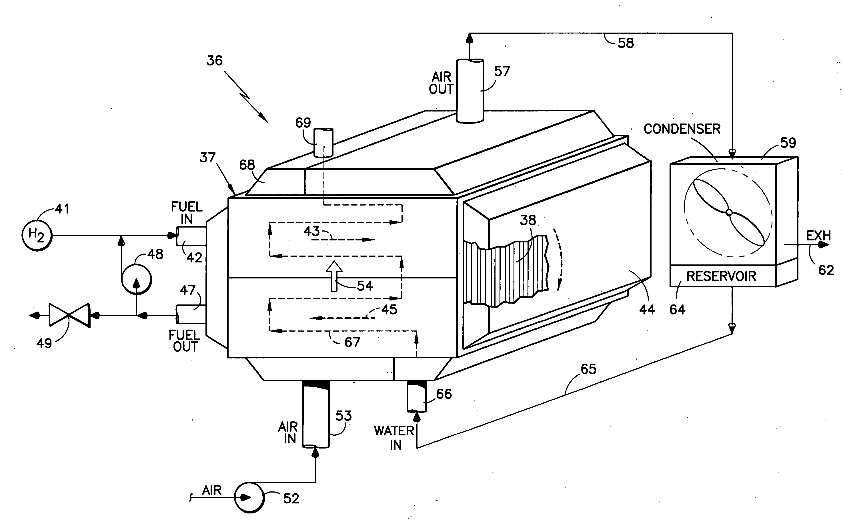
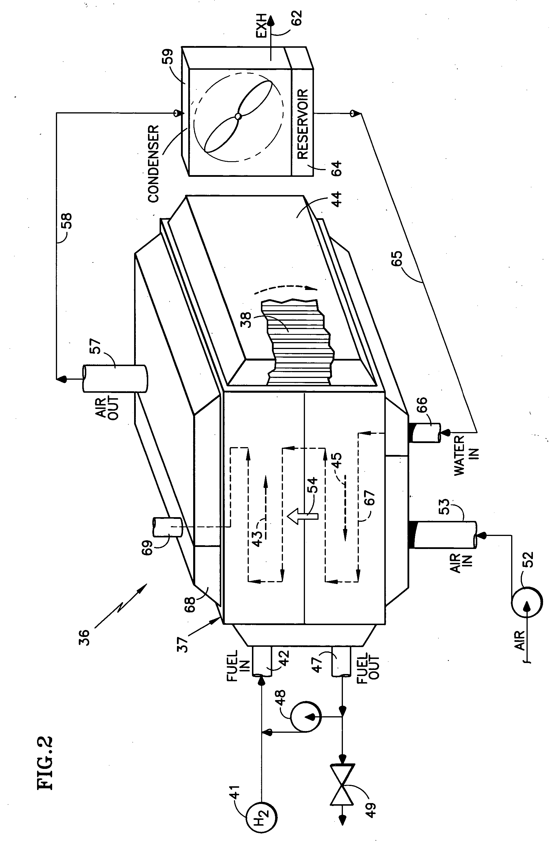
[0029] Referring now to FIG. 2, a fuel cell power plant 36 according to the present invention includes a stack 37 of fuel cells 38 which are shown disposed vertically, although they may be disposed horizontally.

[0030] In this embodiment, fuel from the source 41 is provided to a fuel inlet 42 and flows to the right in a first fuel pass, as indicated by the bold arrow 43, to a fuel turn manifold 44. The fuel gas then flows downwardly and into a second fuel pass of the fuel flow fields, wherein the fuel gas flows to the left as indicated by the bold arrow 45. From a fuel outlet 47, the fuel may flow through a recycle pump 48 (perhaps with valves not shown) back to the fuel inlet 42, and may be periodically purged to ambient through a valve 49, all as is known in the art. Single pass, triple pass or other fuel flow configurations may be used.

[0031] In the embodiment of FIG. 2, air is provided by a pump 52 to an air inlet 53, and the air flows upwardly through the oxidant reactant gas ...


PUM

PropertyMeasurementUnit
Temperatureaaaaaaaaaa
Pressureaaaaaaaaaa
Flow rateaaaaaaaaaa

Abstract

Fuel cells (38) have water passageways (67; 78, 85; 78a, 85a) that provide water through reactant gas flow field plates (74, 81) to cool the fuel cell. The water passageways may be vented to atmosphere (99), by a porous plug (69), or pumped (89, 146) with or without removing any water from the passageways. A condenser (59, 124) receives reactant air exhaust, may have a contiguous reservoir (64, 128), may be vertical, (a vehicle radiator, FIG. 2), may be horizontal, contiguous with the top of the fuel cell stack (37, FIG. 5), or below (124) the fuel cell stack (120). The passageways may be grooves (76, 77; 83, 84) or may comprise a plane of porous hydrophilic material (78a, 85a) contiguous with substantially the entire surface of one or both of the reactant gas flow field plates. Air flow in the condenser may be controlled by shutters (155). The condenser may be a heat exchanger (59a) having freeze-proof liquid flowing through a coil (161) thereof, the amount being controlled by a valve (166). A deionizer (175) may be used.

Description

CROSS REFERENCE TO RELATED APPLICATION [0001] This is a continuation-in-part of U.S. patent application Ser. No. 11 / 027,332 filed Dec. 29, 2004.TECHNICAL FIELD [0002] This invention relates to fuel cells having water passageways that provide water to reactant gas flow passages wherein the water is evaporated in proportion to the waste heat generated in the cells; the water condensed from the exhausted reactant gas is returned to the water passageways, which may be dead-ended or vented, that receive condensate from a condenser which removes water from the air exhausting the cells. BACKGROUND ART [0003] It is known in the fuel cell art to evaporatively cool fuel cells, thereby deriving the benefit of the heat of vaporization, in contrast with conveying sensible heat to circulating water passing through the cells or coolant passing through coolant plates. Typically, prior approaches to evaporative cooling have taken one of two forms. In a first form, water is abundantly atomized or fog...

Claims


Application Information

Patent Timeline
IPC IPC(8): H01M8/02H01M8/04
CPCH01M8/0258H01M8/0267H01M8/04029H01M8/04089Y02E60/50F28D15/0266F28F2245/02H01M8/241H01M8/2457H01M8/2484
Inventor REISER, CARL A.MEYERS, JEREMY P.JOHNSON, DAVID D.EVANS, CRAIG E.DARLING, ROBERT M.SKIBA, TOMMYBALLIET, RYAN J.
Owner AUDI AG
Why Eureka
Try Eureka