Core catcher, manufacturing method thereof, reactor containment vessel and manufacturing method thereof

a manufacturing method and core catcher technology, applied in nuclear engineering problems, greenhouse gas reduction, nuclear elements, etc., can solve the problems of reactor core exposed above water level, insufficient cooling, and water level in the reactor falling,

Active Publication Date: 2013-01-22
KK TOSHIBA
View PDF30 Cites 41 Cited by
  • Summary
  • Abstract
  • Description
  • Claims
  • Application Information

AI Technical Summary

Benefits of technology

[0024]The above and other features and advantage of the present invention will become apparent from the discussion herein below of specific, illustrative embodiments thereof presented in conjunction with accompanying drawings, in which:
[0025]FIG. 1 is a bottom plan view of a steel main body according to a first embodiment of the present invention;
[0026]FIG. 2 is a vertical cross sectional view around a core catcher according to the first embodiment of the present invention;
[0027]FIG. 3 is a vertical cross sectional view of a reactor containment vessel according to the first embodiment of the present invention;
[0028]FIG. 4 is a perspective view of a body sub piece according to a second embodiment of the present invention;
[0029]FIG. 5 is a bottom plan view of a body sub piece according to the second embodiment of the present invention;

Problems solved by technology

In a water cooled reactor, by rundown of water supply into a reactor pressure vessel or a rupture of piping connected to the reactor pressure vessel, a reactor water level may fall, a reactor core may be exposed above the water level and cooling may become insufficient.
However, although it is a very low probability, it can be assumed that the above mentioned emergency core cooling system would not operate and any other devices for supplying water to the reactor core would not be available.
Under such a condition, the reactor core would be exposed due to lowering of the reactor water level and cooling would be insufficient, fuel rod temperature would rise with decay heat generated continuously after shutdown of the nuclear reactor and the reactor core would meltdown eventually.
Therefore, if there is no means for cooling, the core debris heats concrete stretched on the containment vessel floor.
The generated non-condensable gas would pressurize and damage the reactor containment vessel and would damage a containment vessel boundary by melting erosion of concrete or reduce structure toughness of the containment vessel.
As a result, if the reaction of the core debris and the concrete continues, it would result in a breakage of the containment vessel and a radioactive material in the containment vessel would be emitted to the outside.
If a corium is cooled by boiling of water supplied over the corium at a top surface and a deposition thickness of the corium is so thick, it may not be able to cool the corium fully to the bottom of it.
However, a structural design of the containment vessel makes it difficult to expand the floor area sufficiently.
Therefore, as a thermal power of a plant becomes large, necessary floor area of lower drywell becomes large and it becomes more difficult to design the containment vessel.
In case that cooling water is supplied over the top surface of the core debris fallen to the floor of the reactor containment vessel, if an amount of removable heat at the bottom of the core debris is small, temperature at the bottom of the core debris may remain high because of decay heat and erosion of concrete of the containment vessel floor may be unable to be stopped.
However, the core debris might not be cooled sufficiently only by covering with heat resistant member.
And it takes long time and labor to provide a lot of piping for cooling water to run in order to cool the core debris.
So, if deposition thickness of the corium is so large, it may be unable to cool sufficiently to the bottom of the corium.
However, structural design of the containment vessel makes it difficult to provide large enough floor area.

Method used


Image

  • Core catcher, manufacturing method thereof, reactor containment vessel and manufacturing method thereof
  • Core catcher, manufacturing method thereof, reactor containment vessel and manufacturing method thereof
  • Core catcher, manufacturing method thereof, reactor containment vessel and manufacturing method thereof

Examples


first embodiment

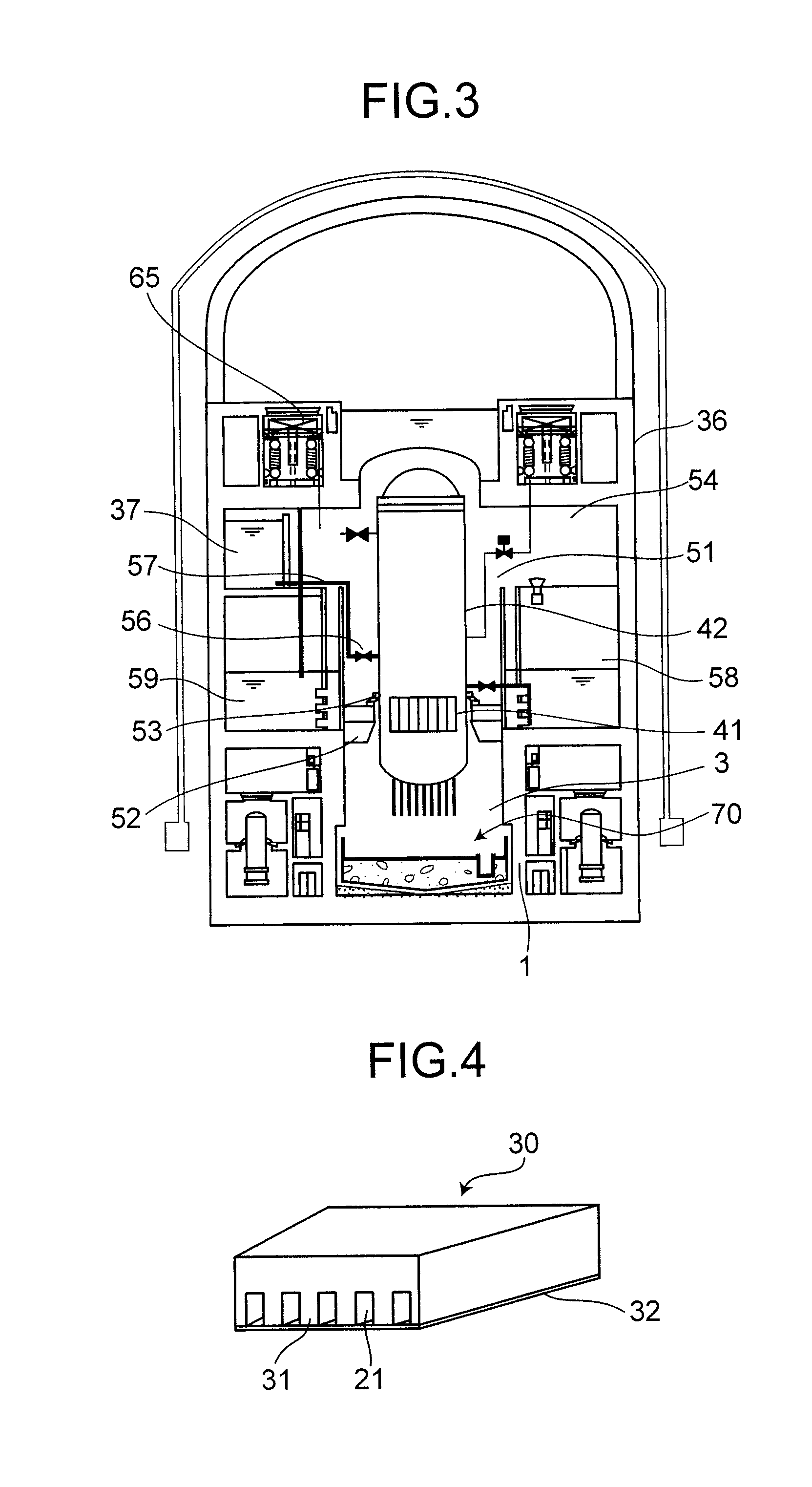
[0060]FIG. 3 is a vertical cross sectional view of a reactor containment vessel according to the first embodiment of the present invention.

[0061]Inside of a reactor containment vessel 36, there is a space called drywell 51. A reactor pressure vessel (RPV) 42 is installed in the drywell 51. The reactor pressure vessel 42 is fixed by RPV support 52 with an RPV skirt 53. Higher part of the drywell 51 than the RPV support 52 is called upper drywell 54 and lower part is called lower drywell 3. Wall surrounding the lower drywell 3 is called a pedestal side wall 1. In an ESBWR, the RPV support 52 is supported by the pedestal side wall 1.

[0062]A reactor core 41 is contained inside the reactor pressure vessel 42.

[0063]A gravity-driven cooling system (GDCS) pool 37 is installed in the upper drywell 54. The GDCS pool 37 and the reactor pressure vessel 42 are connected by piping 57 via a blast valve 56. A pressure suppression chamber 58 is located below the upper drywell 54 and surrounds the re...

second embodiment

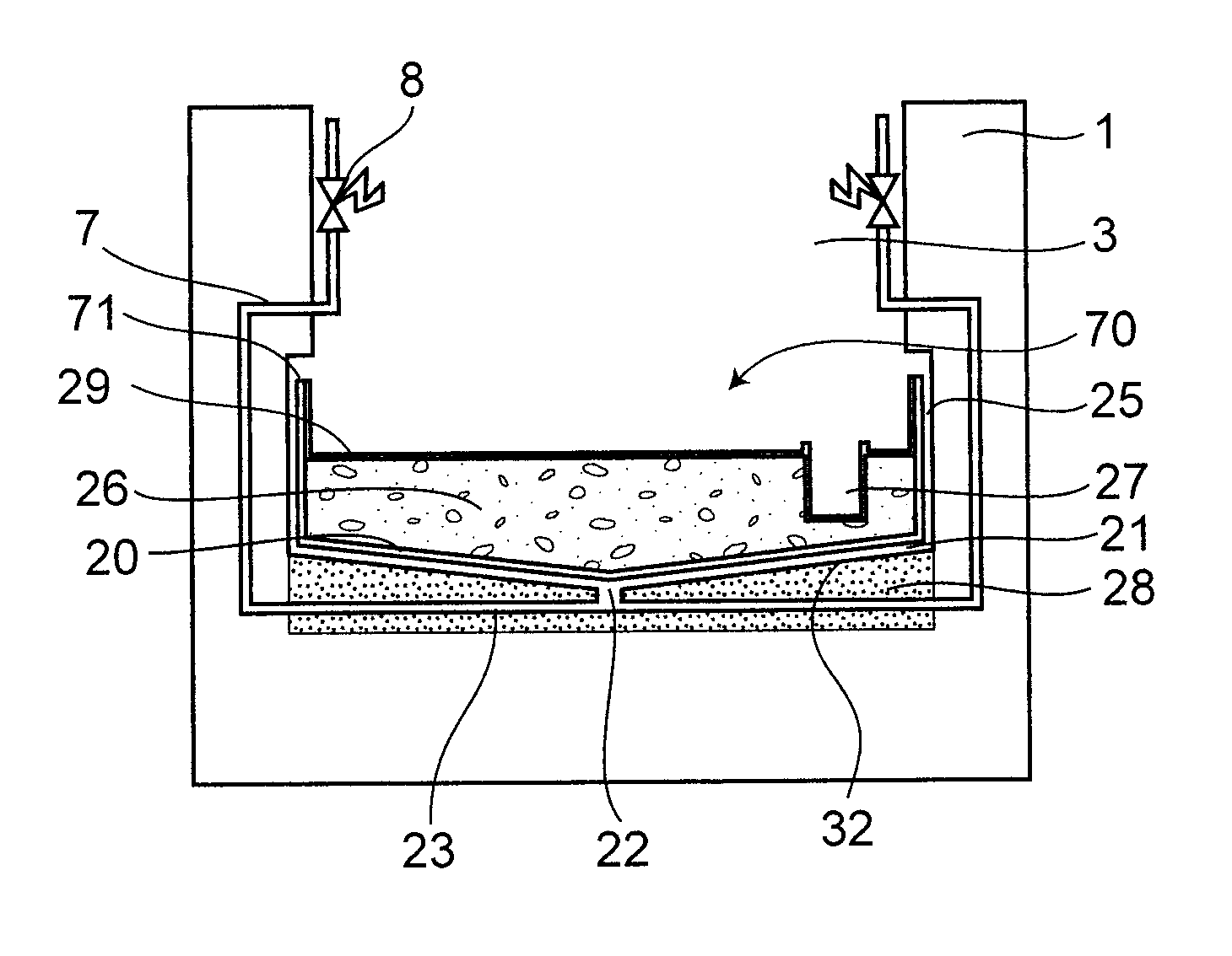
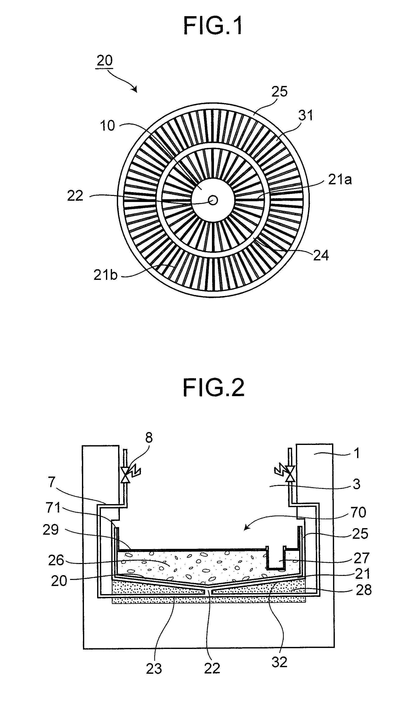
[0095]A core catcher according to a second embodiment of the present invention uses subdivided body sub pieces 30 in combination for easy installation.

[0096]FIG. 4 is a perspective view of the body sub piece 30 and the base lid 32 according to the second embodiment. FIG. 5 is a bottom plan view of the body sub piece 30 according to the second embodiment.

[0097]The cooling fins 31 are formed on a bottom surface of the each body sub pieces 30. The base lid 32 having a same projection shape as the body sub piece 30 is attached to the bottom of the cooling fins 31. Spaces between the cooling fins 31 are the cooling channels 21 through which the cooling water flows.

[0098]The body sub pieces 30 and the cooling fins 31 integrated with the body sub pieces 30 are made of steel and thickness is about 18 cm in total, for example. Thickness of the base lid is about 2 cm and the thickness of whole of the body sub piece 30 is about 40 cm for example. The base lid 32 can be made of any material tha...

third embodiment

[0105]FIG. 8 is a vertical cross sectional view of a reactor containment vessel according to a third embodiment of the present invention.

[0106]A pedestal 115 is formed by a pedestal floor 107 located in the lower part and a surrounding pedestal side wall 124 of cylindrical shape in a reactor containment vessel 102. A reactor pressure vessel 101 containing a reactor core 123 is supported by the pedestal side wall 124.

[0107]A suppression pool 104 is surrounding the pedestal side wall 124 in a lower part of the reactor containment vessel 102. The suppression pool 104 stores water.

[0108]A molten core cooling device (core catcher) 130 is installed on the pedestal floor 107. Cooling water injection piping 108 is connected to the molten core cooling device 130. The cooling water injection piping 108 is connected to a cistern 105 located in an upper part of the reactor containment vessel 102 via an injection valve 114.

[0109]A cooling device 106 is allocated above the reactor containment ves...


PUM


Abstract

Core debris generated during a molten reactor core in a reactor containment vessel penetrating the reactor containment vessel is configured to be caught by a core catcher located beneath the reactor containment vessel which has a main body having first stage cooling water channels and second stage surrounded by cooling fins extending radially. The number of the second stage cooling channels is larger than that of the first stage cooling channels. Cooling water is supplied from a cooling water injection opening and distributed to the first cooling water channels at a distributor. An intermediate header is formed between the first and the second cooling water channels, and the cooling water is distributed to the second cooling water channels uniformly.

Description

CROSS REFERENCE TO RELATED APPLICATION[0001]This application is a continuation-in-part application of International Application No. PCT / JP2007 / 000115, filed Feb. 22, 2007, and claims the benefit of priority from the prior Japanese Patent Application Nos. 2006-44742, 2006-53660 and 2006-279969, filed on Feb. 22, 2006, Feb. 28, 2006 and Oct. 13, 2006, respectively; the entire content of which is incorporated by reference.BACKGROUND OF THE INVENTION[0002]This invention relates to a core catcher, a manufacturing method of a core catcher, a reactor containment vessel and a manufacturing method of a reactor containment vessel.[0003]In a water cooled reactor, by rundown of water supply into a reactor pressure vessel or a rupture of piping connected to the reactor pressure vessel, a reactor water level may fall, a reactor core may be exposed above the water level and cooling may become insufficient. Supposing such a case, it is designed that a nuclear reactor is shut down automatically unde...

Claims


Application Information

Patent Timeline
Patent Type & Authority Patents(United States)
IPC IPC(8): G21C9/00
CPCG21C9/016G21Y2002/201G21C21/00Y02E30/40G21Y2004/30Y02E30/30
Inventor SATO, TAKASHIHAMAZAKI, RYOICHITAHARA, MIKAKOJIMA, YOSHIHIROOIKAWA, HIROHIDEKURITA, TOMOHISAYOKOBORI, SEIICHISUZUKI, YUKA
Owner KK TOSHIBA
Why Eureka
Try Eureka