Cylindrical jacket, jacket hose, suction hose, and cylindrical jacket manufacturing apparatus
a manufacturing apparatus and cylindrical technology, applied in mechanical equipment, weaving, looms, etc., can solve the problems of insufficient control of turbulence, insufficient flexibility and light weight, and inability to ensure the uniformity of the lining layer, and achieve the effect of small pressure loss
- Summary
- Abstract
- Description
- Claims
- Application Information
AI Technical Summary
Benefits of technology
Problems solved by technology
Method used
Image
Examples
embodiment 1
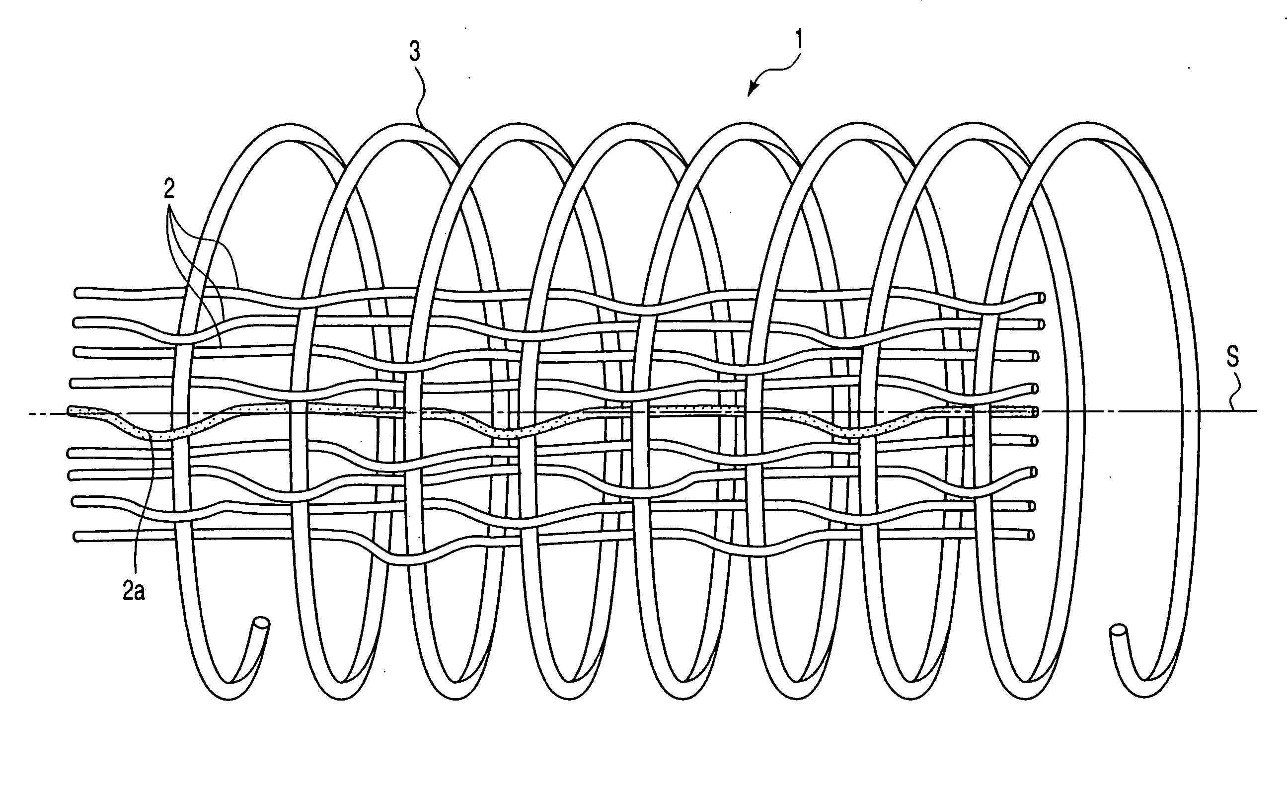
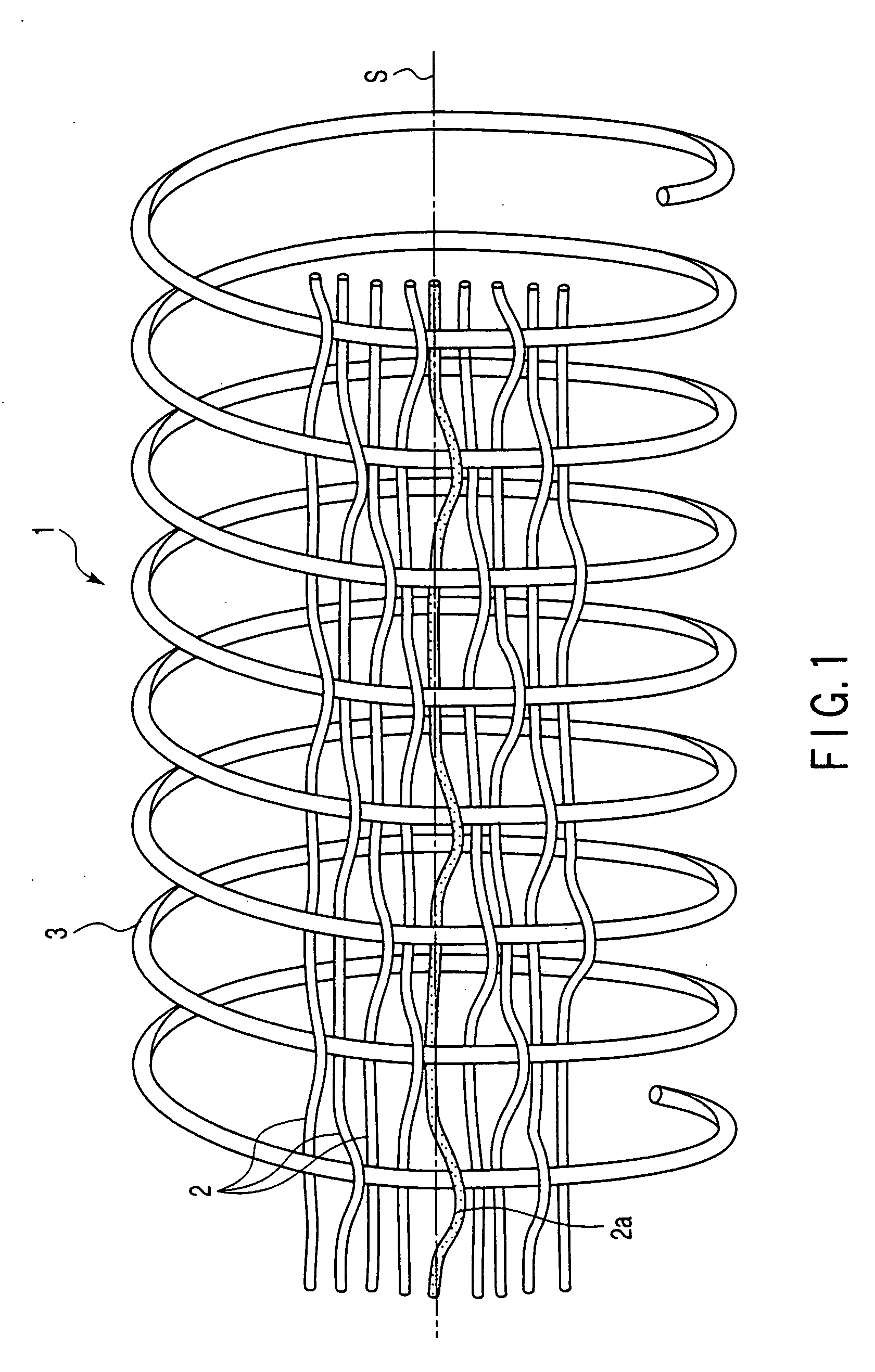
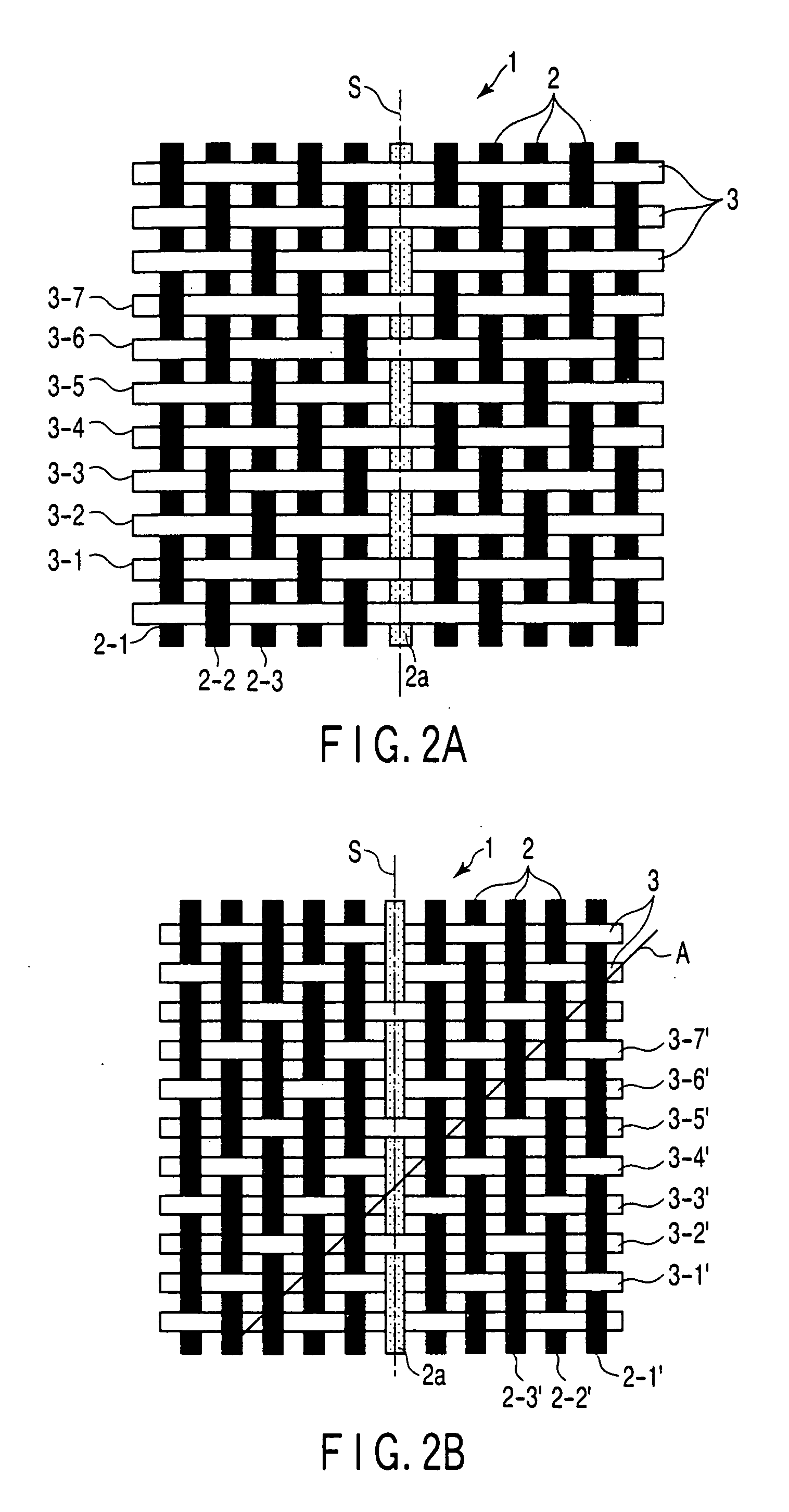
[0048] A configuration of a cylindrical jacket 1 will be explained based on FIGS. 1-4. The jacket is composed of a plurality of warp 2 made of fiber and one weft 3 made of hard steel wire. The warp 2 uses 298 white polyester threads spun into 10 / 10s and one blue shank thread 2a spun into 20 / 10s, for example. The weft 3 uses 1.8-mm-diameter galvanized hard steel, for example, and is driven to have 26 knots per 10 cm. One shank thread 2a out of the warps 2 used here is simply shown to clearly indicate the direction of the warp 2 and the direction of a twill line A formed by the warp 2 woven continuously over the weft 3 when the warp 2 and weft 3 are woven into twill, and is not directly concerned with the present invention. FIGS. 1-3 show the structures of a fabric woven by a one-shuttle cylindrical weaving machine and arranged in one line.
[0049] The cylindrical jacket 1 is remodeled to one-shuttle from the cylindrical weaving machine HM604 made by Mandal in Norway. A plurality of wa...
embodiment 2
[0061] A cylindrical jacket manufacturing apparatus will be explained with reference to FIGS. 6-9, FIG. 6 is a front view of the manufacturing apparatus, FIG. 7 is a left side view of FIG. 6, FIG. 8 is a right side view of FIG. 6, and FIG. 9 is a plane view of a lower part fixing guide, which is one of the components of the manufacturing apparatus of FIG. 6. An upper part fixing guide described later has the same form.
[0062] As shown in FIGS. 6-8, a cylindrical weaving machine 11 is placed at a position, as it were, the second floor. The cylindrical weaving machine 11 is the Mandal HM604, for example. The cylindrical weaving machine 11 has a shuttle (not shown) to weave a weft rotating around a weaving ring 12. The shuttle feeds a weft (not shown) to the inside of the weaving ring 12, which weaves a cylindrical jacket 14 with a warp 13 fed from the outside of the cylindrical weaving machine 11.
[0063] The above manufacturing apparatus has a cylinder twisting mechanism 15, a rotary ...
PUM
 Abstract
Description
Claims
Application Information
 - R&D
- Intellectual Property
- Life Sciences
- Materials
- Tech Scout
- Unparalleled Data Quality
- Higher Quality Content
- 60% Fewer Hallucinations
Browse by: Latest US Patents, China's latest patents, Technical Efficacy Thesaurus, Application Domain, Technology Topic, Popular Technical Reports.
© 2025 PatSnap. All rights reserved.Legal|Privacy policy|Modern Slavery Act Transparency Statement|Sitemap|About US| Contact US: help@patsnap.com


