Slide cover and electronic device having slide cover

a technology of electronic devices and sliding covers, which is applied in the direction of camera filters, instruments, packaged goods, etc., can solve the problems of reducing manufacturing efficiency, affecting the operation of electronic devices, so as to avoid damage to sliding covers, the effect of reducing production costs and reducing production costs

Inactive Publication Date: 2006-07-27
SONY CORP
View PDF1 Cites 13 Cited by
  • Summary
  • Abstract
  • Description
  • Claims
  • Application Information

AI Technical Summary

Benefits of technology

[0022] According to the invention described in claim 7, the electronic device characterized in that the operating projection includes a pushing surface inclined to the moving direction of the holding member, and is supported by the structural member so as to be rotatable; the pushing surface is biased by biasing means interposed between the structural member and the operating projection such that the sides of the pushing surface along the rotational axis are perpendicular to the moving direction of the holding member, and is biased in the direction in which the pushing surface pushes an operation-receiving piece of the switch provided in the body; and the biasing force of the biasing means is large enough to push the operation-receiving piece of the switch. Accordingly, even with variations in the clearance between the sliding cover and the body, the operating projection can reliably push the operation-receiving piece of the switch provided in the body by disposing the operating projection so as to protrude toward the body by a somewhat larger amount. Also, even when the operating projection is too close to the body, the operating projection can reliably operate by rotating the operating projection against the biasing force, and damage to the operating projection, the sliding cover, the body, and the like can be avoided.
[0023] According to the invention described in claim 8, the electronic device is characterized in that the operating projection is formed of a spring having a pushing surface inclined to the moving direction of the holding member, the pushing surface is resilient to the moving direction of the holding member, and the resilience is large enough to push the operation-receiving piece of the switch. Accordingly, even with variations in the clearance between the sliding cover and the body, the operating projection can reliably push the operation-receiving piece of the switch provided in the body by disposing the operating projection so as to protrude toward the body by a somewhat larger amount. Also, even when the operating projection is too close to the body, the operating projection bends due to the resilience of the spring. Thus, the operating projection can reliably push the operation-receiving piece of the switch, and damage to the operating projection, the sliding cover, the body, and the like can be avoided.

Problems solved by technology

However, the overall structure cannot be made compact, and has poor assembling workability.
Therefore, it is time consuming to assemble the lens cover (2) into the optical device body (1), and this causes lower manufacturing efficiency and an increase in costs.

Method used


Image

  • Slide cover and electronic device having slide cover
  • Slide cover and electronic device having slide cover
  • Slide cover and electronic device having slide cover

Examples


first embodiment

[0045] FIGS. 1 to 18 illustrate the present invention.

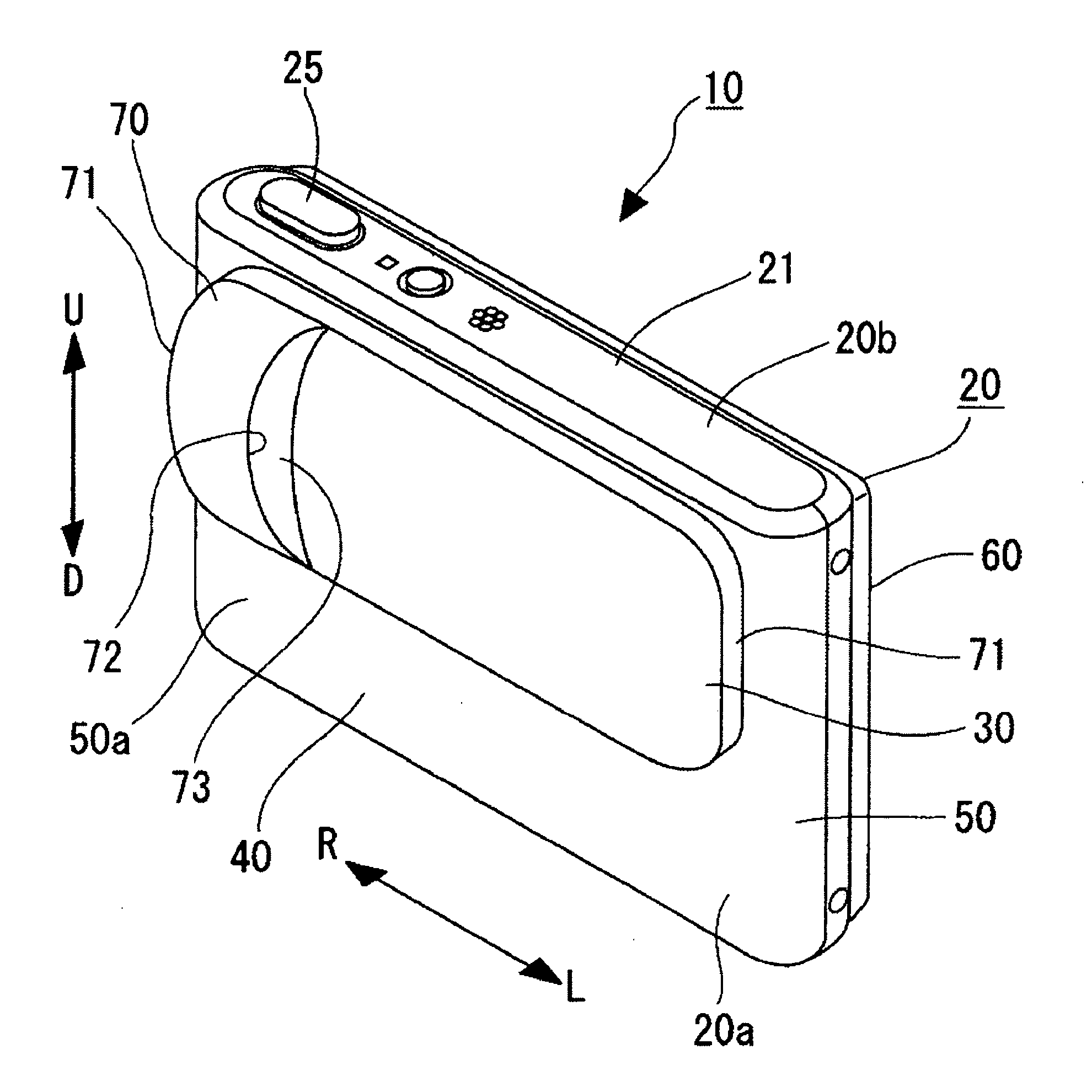
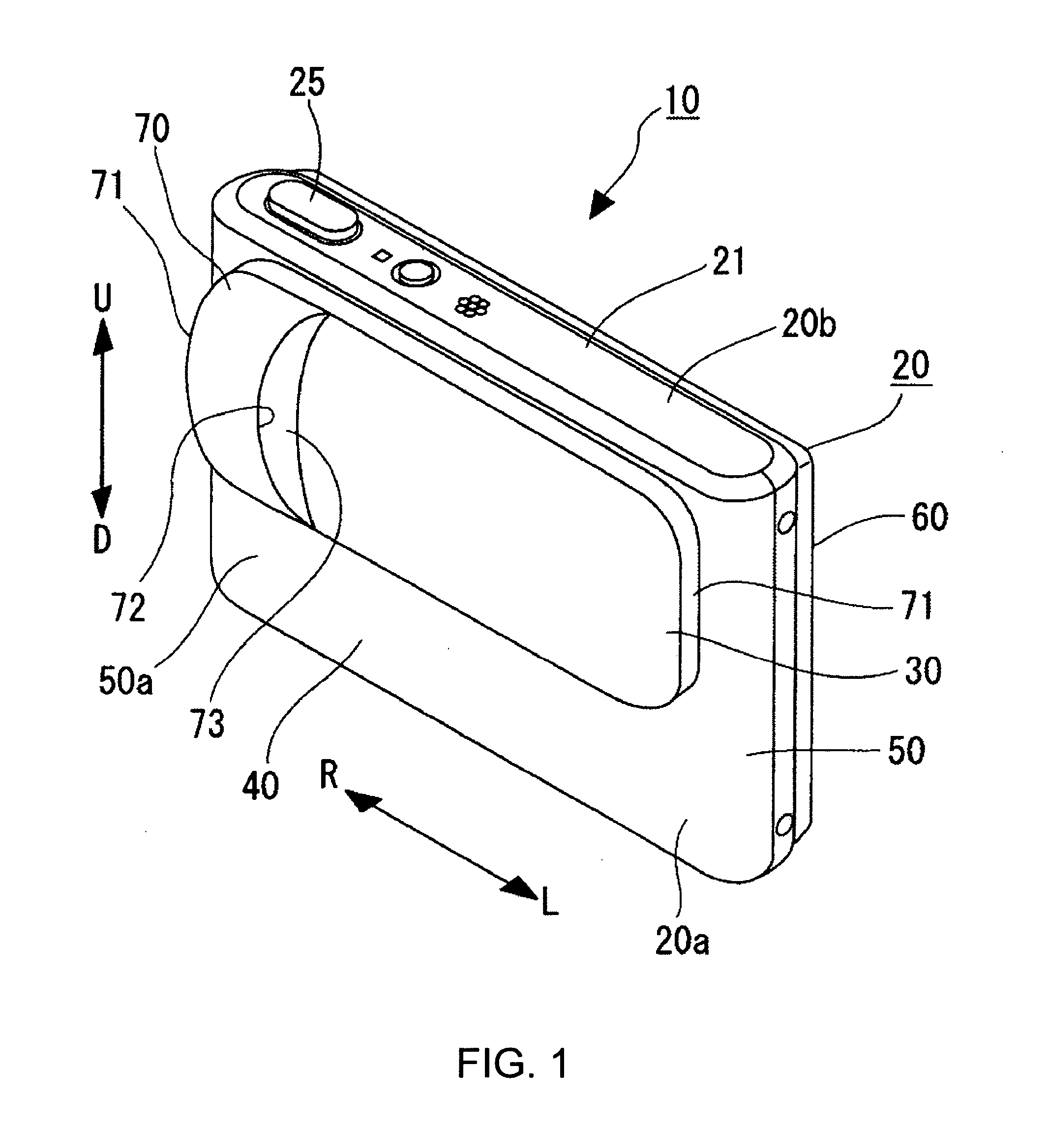
[0046] With reference to FIGS. 1 to 3, a digital camera 10 includes a body 20, and a sliding cover 30 (strictly speaking, parts of the sliding cover 30) attached to the front surface 20a of the body 20 so as to be movable in the vertical direction, i.e. in the direction of a double-headed arrow U-D shown in FIG. 1.

[0047] The body 20 is a rectangle that is slightly longer in the horizontal direction, i.e. in the direction of an double-headed arrow L-R shown in the drawings, and is formed of a flat casing 40 that is thinner in the width direction and that contains required components and members disposed therein. The casing 40 includes a front case 50 and a rear case 60 joined together. The upper end of the casing 40 is closed with a top plate 21, and the lower end is closed with a bottom plate 22 (see FIG. 3).

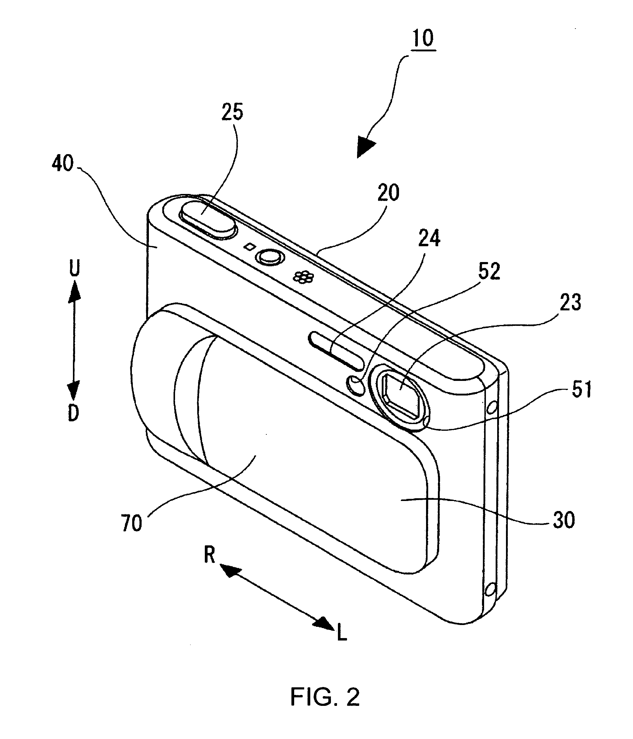
[0048] An approximately circular opening 51 is disposed on the upper left of the front surface 20a of the body 20. The fr...


PUM


Abstract

A sliding cover 30 includes an outside plate 70, a structural member 80 fixed to the rear face of the outside plate, a movable holding member 90 disposed in a space between the outside plate and the structural member, and toggling means 100 disposed between the holding member and the outside plate or the structural member. The holding member includes two parallel racks 82a and 82b, and guiding portions 81 disposed at both end portions and extending in the same direction as the racks. The holding member includes a holding plate 91; an even number of pinions 92a and 92b meshed with each other and supported by the holding plate so as to be rotatable; and guiding components 93 supported by the holding plate, the even number of pinions being disposed between the guiding components. The pinions located at both ends are meshed with the racks, and the guiding components are engaged with the guiding portions so as to be slidable. The biasing direction in which the toggling means biases the holding member is reversed substantially at the midpoint of the movable range of the holding member.

Description

TECHNICAL FIELD [0001] The present invention relates to novel sliding covers and electronic devices having sliding covers. In particular, the present invention provides thin sliding covers that can be stably and smoothly opened and closed and that can be easily attached to device bodies, and electronic devices provided with the above-described sliding covers. BACKGROUND ART [0002] A variety of electronic devices include sliding covers that open and close sections to be blocked. In such devices, for example, the sections to be blocked are protected by retaining the sliding covers in a closed state when the devices are not in use, and the sections are exposed by changing the state of the sliding covers to an open state when the devices are in use. For example, digital cameras include sliding covers for opening and closing lens sections and strobe sections. The sliding covers are retained in the closed state so as to cover the lens sections and the strobe sections when the digital came...

Claims


Application Information

Patent Timeline
Patent Type & Authority Applications(United States)
IPC IPC(8): B65D85/38G03B17/02G03B11/04G03B17/04G12B9/02H04N5/225
CPCG03B17/04H04N5/2251H04N23/50G03B11/04G03B17/02H04N23/00
Inventor YANAGISAWA, MICHINOBUMIYAI, HIROKUNINAKAJYOU, TAKUYAUENO, HIROKI
Owner SONY CORP
Why Eureka
Try Eureka