Switching power source device of resonance type

Active Publication Date: 2006-07-27
SANKEN ELECTRIC CO LTD
View PDF11 Cites 22 Cited by
  • Summary
  • Abstract
  • Description
  • Claims
  • Application Information

AI Technical Summary

Benefits of technology

[0020] The switching power source device of resonance type according to the present invention comprises: a DC power source (1); first and second switching elements (3, 4) connected in series to DC power source (1); a primary winding (9a) of a transformer (9) connected in parallel to one of first and second switching elements (3, 4); a resonance capacitor (8) for forming a series circuit together with primary winding (9a) of transformer (9); a rectifying smoother (7) connected to a second winding (9b, 9c) of transformer (9) for supplying DC power to a load (13); an output voltage detector (18) for detecting output voltage on load (13) to produce a detection signal; and a control circuit (2) for applying on-off signals (Vg1, Vg2) to each control terminal of first and second switching elements (3, 4) in response to the detection signal from the output voltage detector (18). Control circuit (2) comprises a frequency control circuit (23) for controlling the on-off operation of first

Problems solved by technology

This results in increase in switching energy loss by control circuit or MOS-FETs as switching elements, and therefore the power source device is disadvantageous in that it has the lower energy conversion efficiency during the light load period than those of sw

Method used


Image

  • Switching power source device of resonance type
  • Switching power source device of resonance type
  • Switching power source device of resonance type

Examples


Embodiment Construction

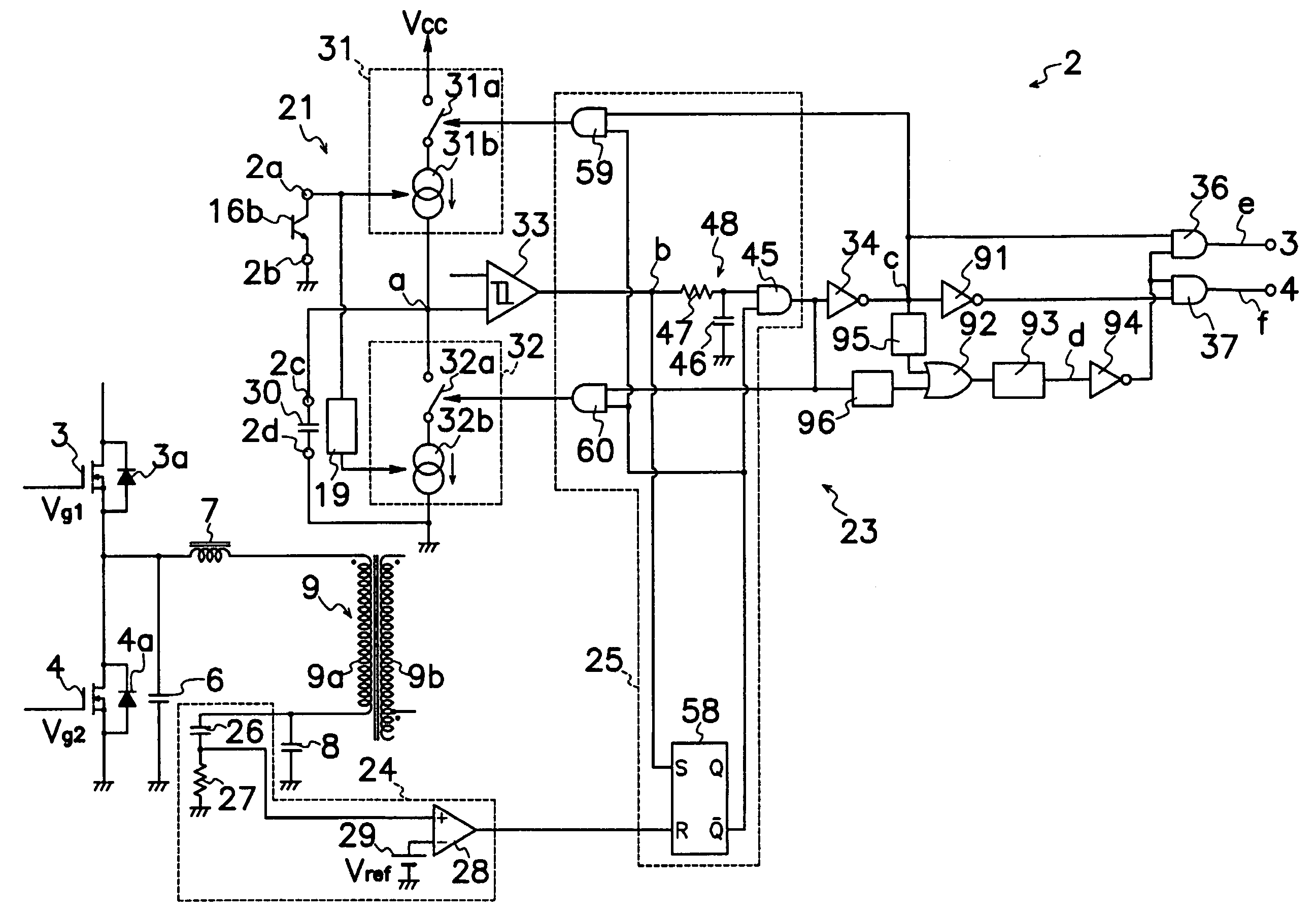
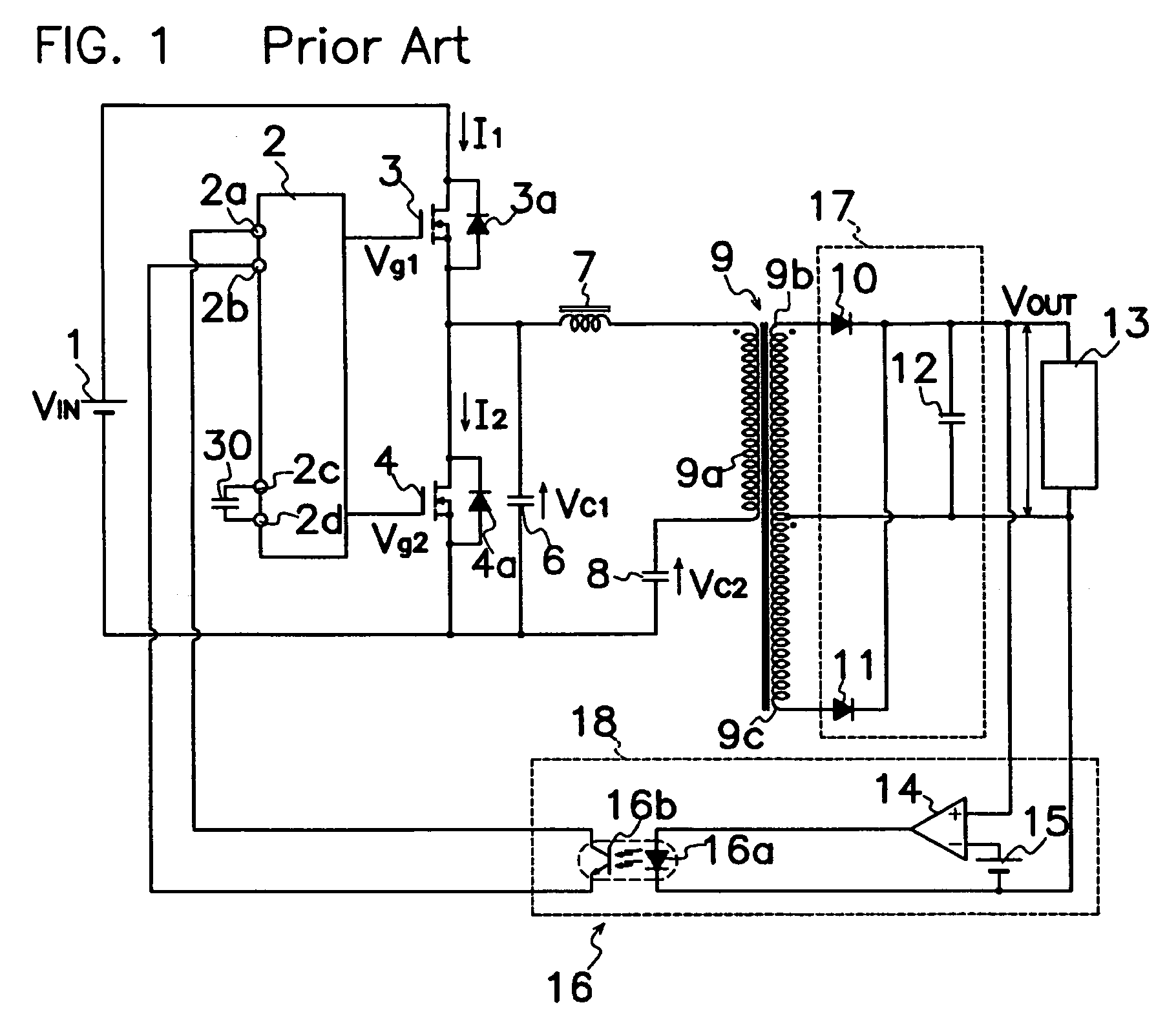
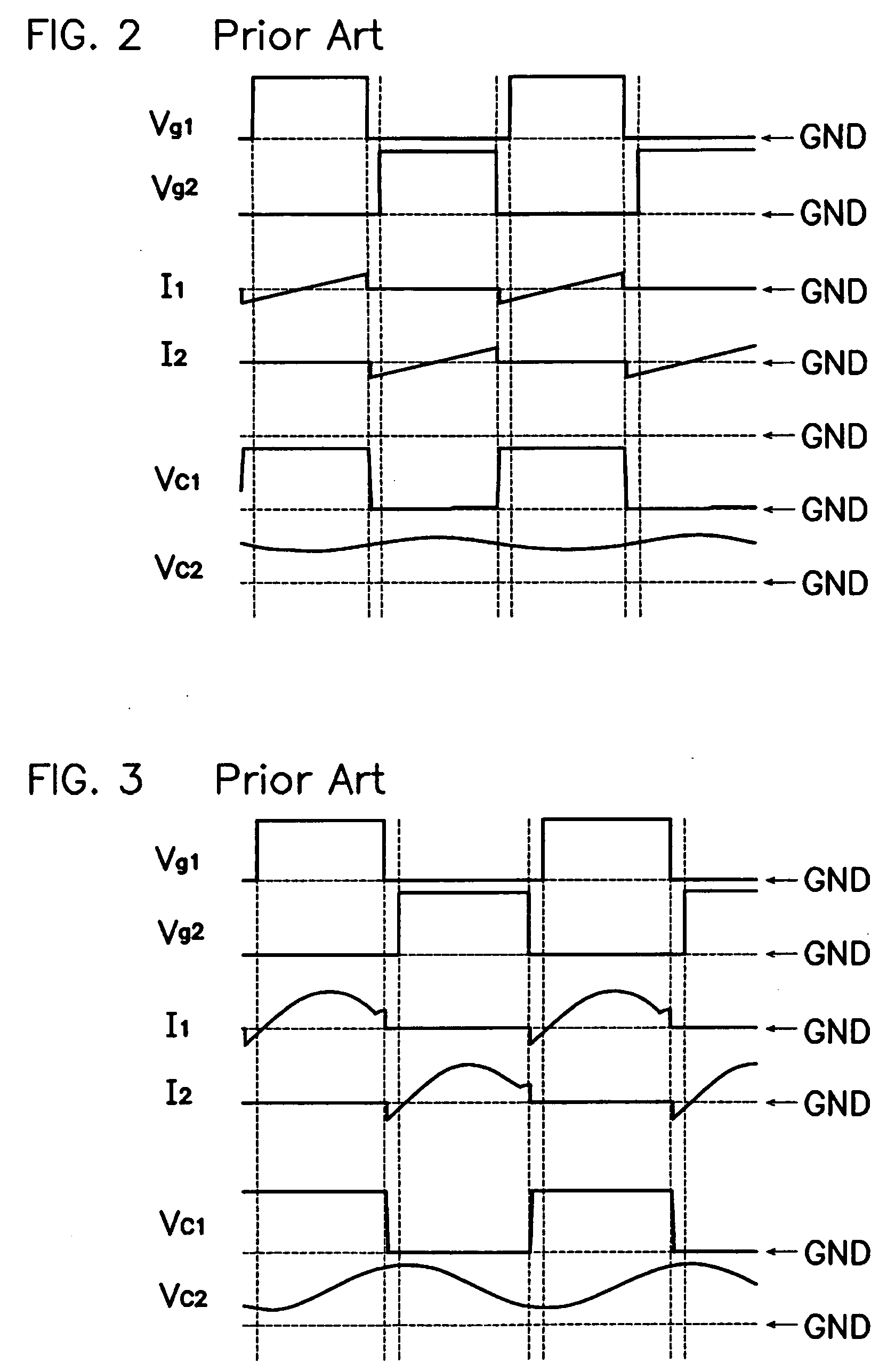
[0038] Embodiments of the switching power source device of resonance type according to the present invention will be described hereinafter in connection with FIGS. 8 to 16 of the drawings. Same reference symbols as those shown in FIGS. 1 and 8 are applied to similar portions in these drawings, omitting explanation therefor. A general and basic circuit of the switching power source device of resonance type according to the present invention is similar to that shown in FIG. 1.

[0039] As shown in FIG. 8, the control circuit 2 according to an embodiment of the present invention, comprises a frequency control circuit 23 for controlling the on-off operation of first MOS-FET (high side switching element) 3 and second MOS-FET (low side switching element) 4 in response to the level of detection signal from output voltage detector 18 to decide the switching frequency. Frequency control circuit 23 comprises a regulatory capacitor 30, and a conduction or on-time control circuit 21 for controlli...


PUM


Abstract

A switching power source device of resonance type is provided which comprises an output voltage detector 18 for detecting output voltage on a load 13 to produce a detection signal; and a control circuit 2 for applying on-off signals Vg1, Vg2 to each control terminal of first and second MOS-FETs 3, 4 in response to the detection signal from the output voltage detector 18. Control circuit 2 comprises a frequency control circuit 23 for controlling the on-off operation of first and second MOS-FETs 3, 4 in response to the level of detection signal from output voltage detector 18 to decide the switching frequency of first and second MOS-FETs 3, 4. Frequency control circuit 23 is provided with an on-time control circuit 21 which more reduces the on-span of one of first and second MOS-FETs 3, 4 during the light load period in response to the level of detection signal from output voltage detector 18 than during the non-light load period to control power consumption, reduce switching loss and noise, and improve switching efficiency in electronics.

Description

TECHNICAL FIELD [0001] This invention relates to a switching power source device of resonance type, in particular, capable of reducing its electric power consumption during the light load condition. BACKGROUND OF THE INVENTION [0002] As shown in FIG. 1, a prior art switching power source device of resonance type comprises a DC power source 1; first and second MOS-FETs 3 and 4 as first and second switching elements connected in series to DC power source 1; a series circuit which includes a resonance reactor or choke coil 7, a primary winding 9a of a transformer 9 and a capacitor 8 connected in series to each other and to two junctions between first and second MOS-FETs 3 and 4 and between second MOS-FET 4 and power source 1; a rectifying smoother 17 connected to secondary windings 9b and 9c of transformer 9 to supply DC power to a load 13; an output voltage detector 18 for detecting an output voltage applied on load 13; and a control circuit 2 for applying on-off signals Vg1, Vg2 to e...

Claims


Application Information

Patent Timeline
IPC IPC(8): H02M3/335
CPCH02M3/33523H02M3/337H02M3/33571H02M3/01
Inventor FUKUMOTO, YUKINARI
Owner SANKEN ELECTRIC CO LTD
Why Eureka
Try Eureka