Microfluidic sensors and methods for making the same

a microfluidic sensor and microfluidic channel technology, applied in the field of microfluidic sensors, can solve the problems of inefficiency of multiple required passes of an analytical light beam through such microfluidic channels, cumbersome and delicate systems, and inability to accurately analyze etc., to achieve robust and lightweight construction, facilitate the effect of efficient analysis of small volumes of fluids

Active Publication Date: 2006-07-27
LUCENT TECH INC
View PDF26 Cites 34 Cited by
  • Summary
  • Abstract
  • Description
  • Claims
  • Application Information

AI Technical Summary

Benefits of technology

[0003] There is a continuing need for microfluidic sensors that facilitate the efficient analysis of small volumes of fluids. Among the desired features in such sensors are elimination of ...

Problems solved by technology

Such systems are necessarily complex, and may therefore be both cumbersome and delicate.
However, the ineffi...

Method used


Image

  • Microfluidic sensors and methods for making the same
  • Microfluidic sensors and methods for making the same
  • Microfluidic sensors and methods for making the same

Examples


Embodiment Construction

[0022] The present invention will now be described more fully with reference to the accompanying drawings, in which several presently preferred embodiments of the invention are shown. This invention may, however, be embodied in various forms and should not be construed as being limited to the embodiments set forth herein.

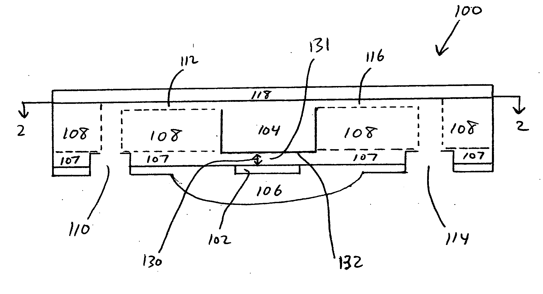
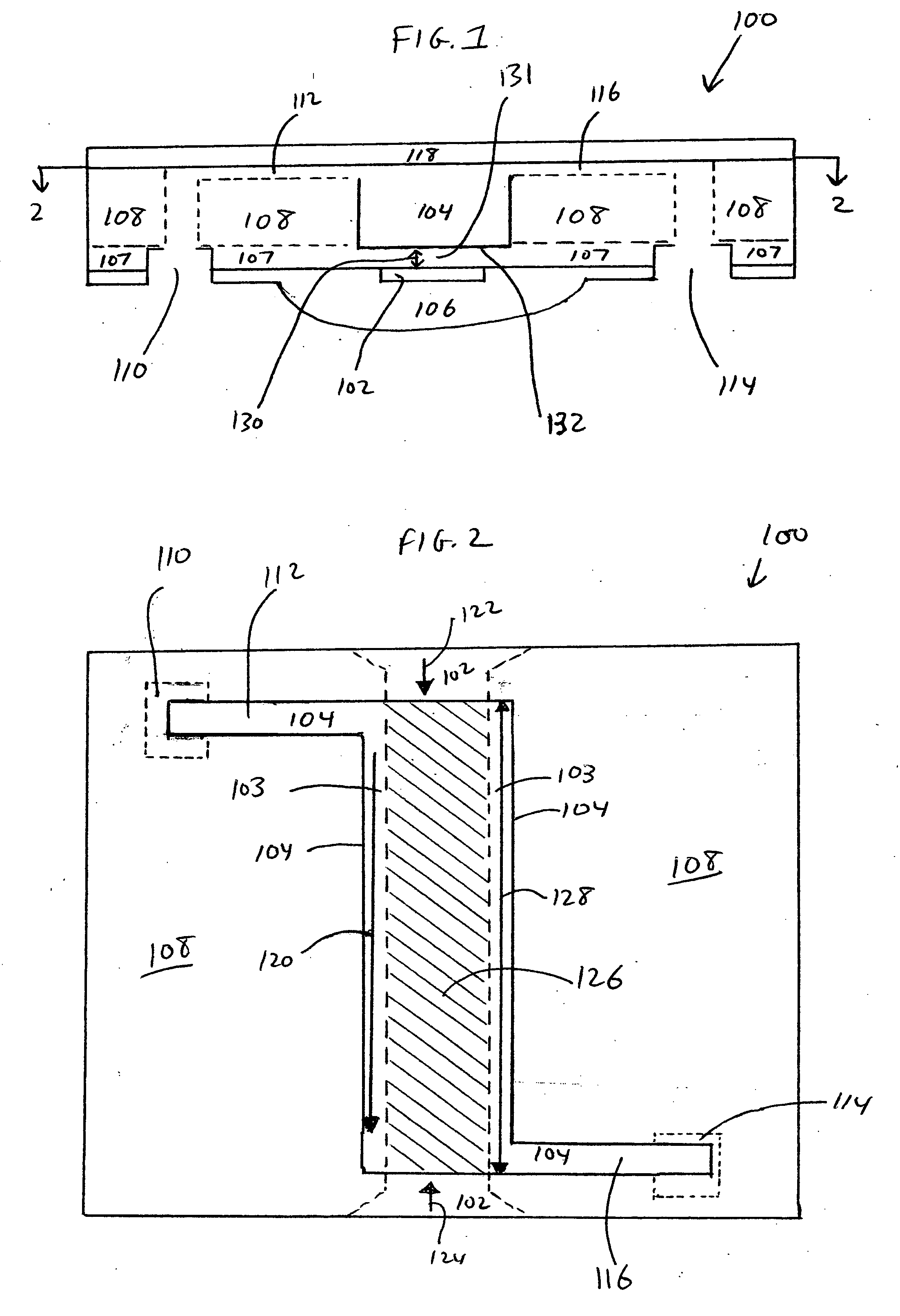
[0023] The present invention provides microfluidic optical sensors and methods for making and using the same. The microfluidic optical sensors facilitate interaction between a fluid to be subjected to optical detection, and light that is employed in the detection. The microfluidic optical sensors provide a high level of interaction between the evanescent field of detector light and a small amount of analyte fluid. Hence, the microfluidic optical sensors provide high detection sensitivity. Small volumes of analyte fluids, as well as analyte fluids comprising small concentrations of target analytes, can thus be effectively analyzed by the microfluidic optical detecto...


PUM


Abstract

Microfluidic optical sensor comprising: an optical waveguide capable of propagating light from an optical input port to an optical output port, the optical waveguide comprising an optical waveguide interaction region; a fluidic channel capable of conducting a fluid from a fluid input port to a fluid output port, the fluidic channel comprising a fluidic channel region; the fluidic channel region being separated from the optical waveguide interaction region by an interposed spacing material configured to transmit an evanescent field of the light through the spacing material between the optical waveguide interaction region and the fluidic channel region. Microfluidic optical sensor comprising an optical resonator. Methods for making microfluidic optical sensors.

Description

FIELD OF THE INVENTION [0001] The present invention relates to the field of microfluidic sensors and to methods for making such sensors. BACKGROUND OF THE INVENTION [0002] Microfluidic sensors have been fabricated in order to optically analyze small samples of fluids. For example, sensors have been made comprising a cuvette having optically neutral walls in which a small sample of a fluid to be analyzed is placed, and then a light beam is directed through the cuvette so that properties of the fluid such as the optical refraction, absorption and transmission characteristics can be detected by analysis of the transmitted and emitted light. Since the cuvettes are relatively small in order to place a small fluid sample in position for passage therethrough of a light beam, the path length of the light beam through the fluid in the cuvette is short. Moreover, the diameter of the light beam is generally small, so that the interaction cross-section between the fluid and the light beam also ...

Claims


Application Information

Patent Timeline
IPC IPC(8): G02B6/00
CPCB01L3/502715B01L2300/0654B01L2300/0816G01N21/0303G01N21/05G01N21/552G01N21/648G01N21/7703G01N2021/056G01N2021/7763G01N2021/7779G01N2021/7783G01N2021/7786G02B6/122G02B2006/12138G01N2021/0346
Inventor PAU, STANLEYEARNSHAW, MARK P.
Owner LUCENT TECH INC
Why Eureka
Try Eureka