Hyddogen generating apparatus
a technology of generating apparatus and hydrogen, which is applied in the direction of machines/engines, chemical/physical/physico-chemical stationary reactors, process and machine control, etc., can solve the problem of not taking out hydrogen safely with age, and achieve the effect of stable operation
- Summary
- Abstract
- Description
- Claims
- Application Information
AI Technical Summary
Benefits of technology
Problems solved by technology
Method used
Image
Examples
first embodiment
[0024] Next, a first embodiment of a hydrogen generating apparatus according to the present invention will be explained referring to figures.
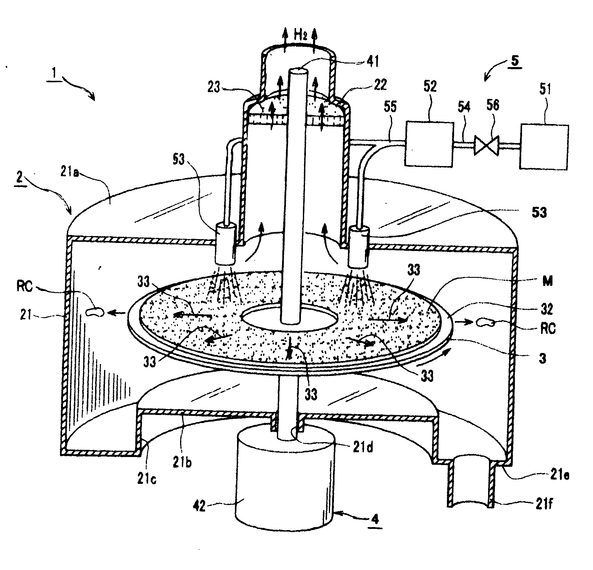
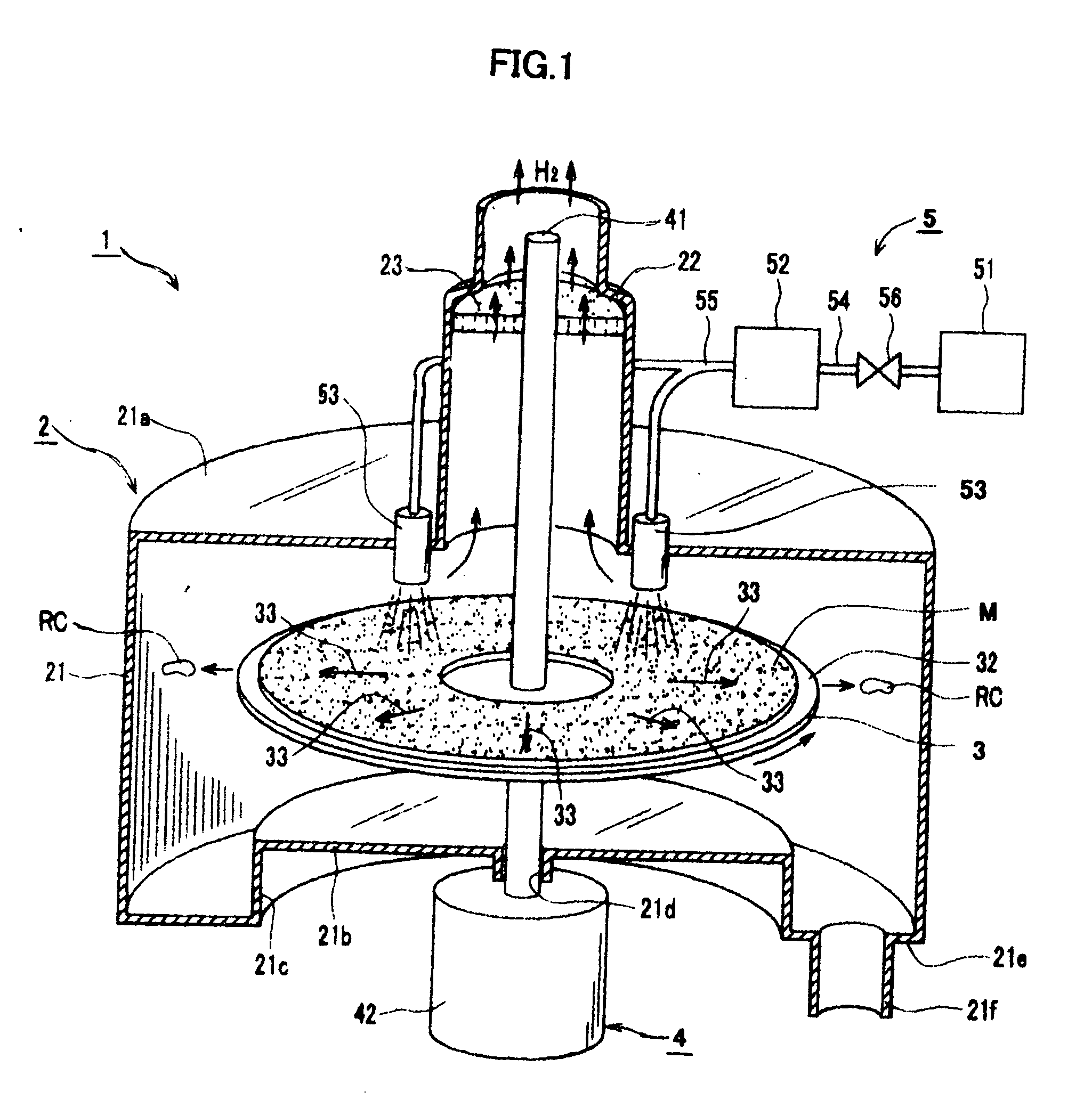
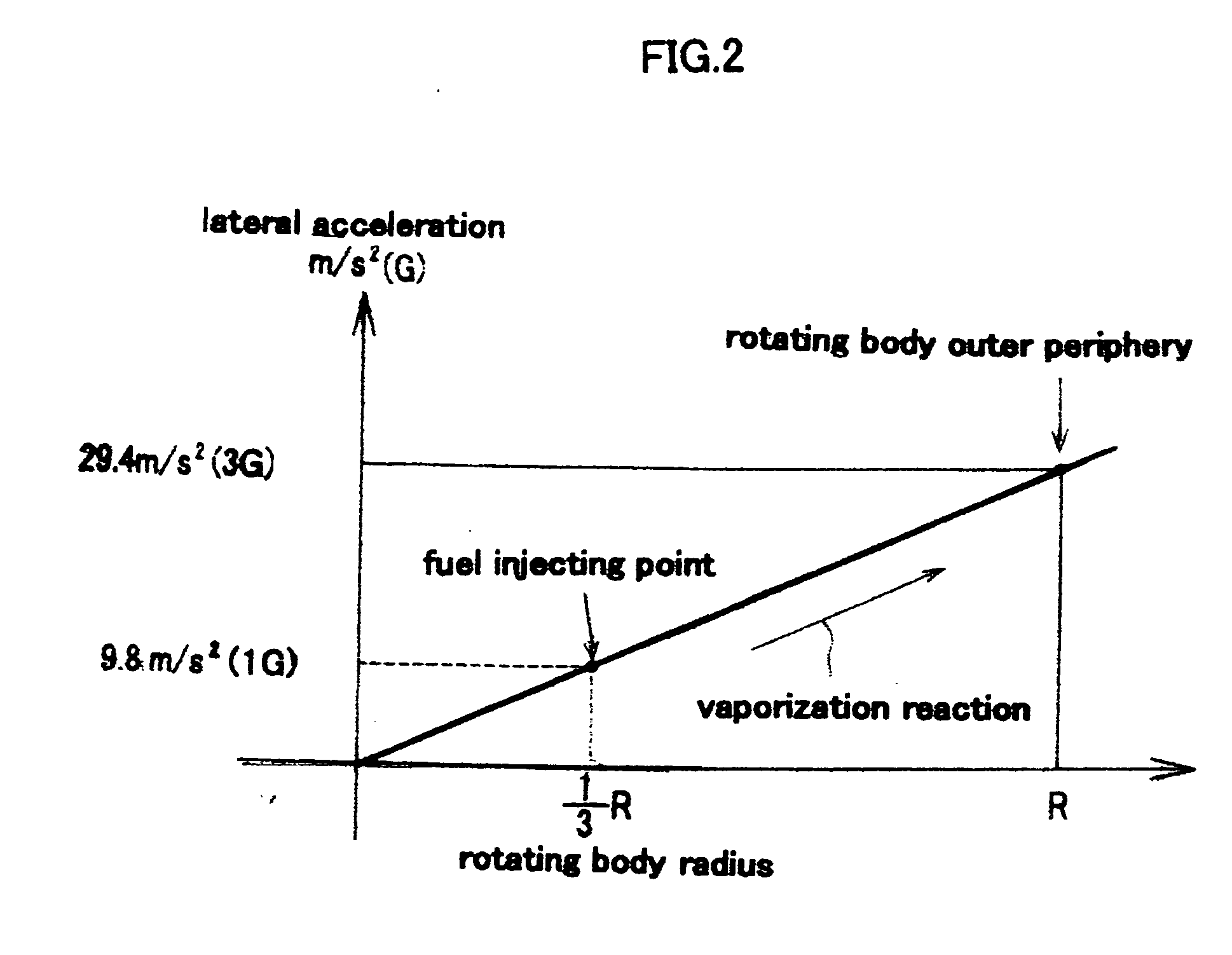
[0025]FIG. 1 is a perspective view showing a first embodiment of a hydrogen generating apparatus according to the present invention. FIG. 2 is a graph showing a relationship between a radial direction position of a rotating disk and a lateral acceleration, which received by a fuel and a reactive compound on the rotating disk.
[0026] As shown in FIG. 1, a hydrogen generating apparatus 1 in which by reacting a solid type catalyst M and a liquid type borohydride fuel (hereinafter, it is said merely as “fuel”), hydrogen is generated.
[0027] The hydrogen generating apparatus 1 comprises mainly a reactor 2 being a hollow case for accommodating the catalyst M, a rotating disk (a rotating body) 3 for fixing the catalyst M, a motor (a rotation driving means) 4 for rotating the rotating disk 3, and a fuel injecting means 5 for blowing the fuel against t...
second embodiment
[0049] Hereafter, a second embodiment of a hydrogen generating apparatus according to the present invention will be explained.
[0050] Since this second embodiment is performed according to the alternation of the first embodiment of the hydrogen generating apparatus 1, the constituting elements similarly to those of the first embodiment are expressed with same reference numerals shown in the first embodiment. FIG. 5 is a cross-sectional view showing a second embodiment of a hydrogen generating apparatus according to the present invention.
[0051] As shown in FIG. 5, a hydrogen generating apparatus 1′ comprises a reactor 2′, a cone body (a rotating body) 6, and a catalyst M′, they have different structures shown in the first embodiment. The reactor 2′ has a cone cylindrical portion 25, which is formed as one body between the rotating disk receiving portion 21 and the projecting portion 22.
[0052] The cone cylindrical portion 25 is formed with a cylindrical-like shape one, in which a di...
third embodiment
[0063] Hereinafter, a third embodiment of a hydrogen generating apparatus according to the present invention will be explained. This third embodiment according to the present invention, a whole fuel flow passages of the hydrogen generating apparatus according the first embodiment of the present invention is cleaning controlled, in addition to the cleaning effect of the contacting area according to the above stated centrifugal separation, it has a cycle for cleaning compulsory the spent fuel flow passage.
[0064] In this third embodiment according to the present invention, the constituting elements similarly to the first embodiment are added the same reference numerals, and the explanations will be omitted.
[0065]FIG. 7 is a perspective view showing the hydrogen generating apparatus according to the third embodiment according to the present invention, and FIG. 8 is a time chart showing operating conditions of the respective valves shown in FIG. 7.
[0066] As shown in FIG. 7, the hydrog...
PUM
| Property | Measurement | Unit |
|---|---|---|
| velocity | aaaaa | aaaaa |
| time T2 | aaaaa | aaaaa |
| time | aaaaa | aaaaa |
Abstract
Description
Claims
Application Information
 - R&D
- Intellectual Property
- Life Sciences
- Materials
- Tech Scout
- Unparalleled Data Quality
- Higher Quality Content
- 60% Fewer Hallucinations
Browse by: Latest US Patents, China's latest patents, Technical Efficacy Thesaurus, Application Domain, Technology Topic, Popular Technical Reports.
© 2025 PatSnap. All rights reserved.Legal|Privacy policy|Modern Slavery Act Transparency Statement|Sitemap|About US| Contact US: help@patsnap.com


