
Eureka
For R&D, Eureka makes reading and utilizing patents & technical documents easy.
Eureka AIR
Designed for self-driven R&D workflows. Generate viable solutions, solve complex R&D challenges, empower your innovation with AI.

Eureka Materials
Designed for material experts only. Revolutionize your material R&D, from search, analyze, to developing new materials.

TechResearch
Generate reliable direction feasibility study reports for your R&D in just a few steps.

TechSeek
Discover and master advanced knowledge NOW. Basics, ideas, possibilities, all at once.

TechMind
As an expert in R&D Theories, TechMind can generates customized viable solutions instantly.

TechRisk
Analyze your overall solution with one click, know your potential R&D risks in advance.

TechMonitor
Get weekly tech updates, stay abreast of the latest tech innovations and key insights.
High frequency receiving circuit provided with controller for turning on and off power supply to local oscillator
- Summary
- Abstract
- Description
- Claims
- Application Information
AI Technical Summary
Benefits of technology
Problems solved by technology
Method used
Image

Examples
first preferred embodiment
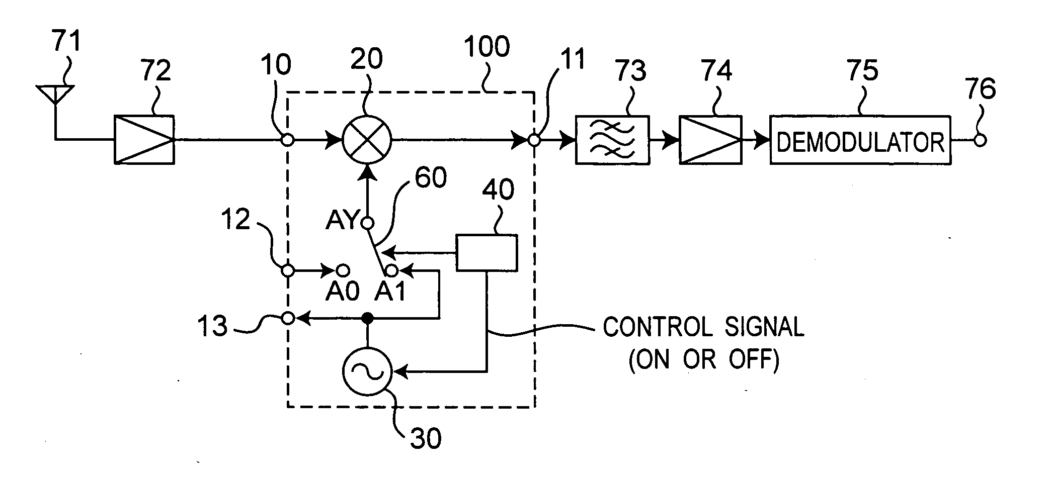
[0047]FIG. 1 is a block diagram showing a configuration of a radio receiving apparatus according to a first preferred embodiment of the present invention. The radio receiving apparatus of FIG. 1 is characterized by including a receiving circuit having a frequency converter 100 instead of the frequency converter 400 and the local oscillator 31, as compared with the radio receiving apparatus shown in FIG. 9. The description will be made mainly on differences from the radio receiving apparatus shown in FIG. 9 hereinafter. In this case, the frequency converter 100 is provided with a high frequency signal input terminal 10, a frequency-converted signal output terminal 11, an oscillation signal input terminal 12, an oscillation signal output terminal 13, a mixer 20, a local oscillator 30, and a control circuit 40.
[0048] Referring to FIG. 1, a radio signal received by an antenna 71 is inputted via a high frequency amplifier 72 to a first input terminal of the mixer 20 through the high fre...
second preferred embodiment
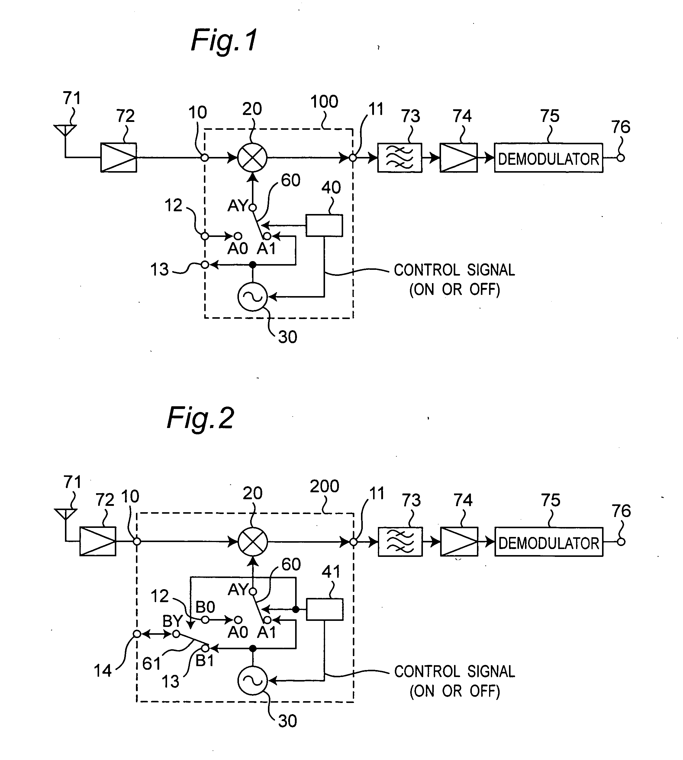
[0055]FIG. 2 is a block diagram showing a configuration of a radio receiving apparatus according to a second preferred embodiment of the present invention. The radio receiving apparatus of FIG. 2 is characterized by including a frequency converter 200 instead of the frequency converter 100 as compared with the radio receiving apparatus shown in FIG. 1. In this case, the frequency converter 200 is provided with a high frequency signal input terminal 10, a frequency-converted signal output terminal 11, an oscillation signal input terminal 12, an oscillation signal output terminal 13, an oscillation signal input and output terminal 14, two switch circuits 60 and 61, and a control circuit 41.
[0056] Referring to FIG. 2, a local oscillation signal generated by a local oscillator 30 is outputted to a contact B1 serving as the oscillation signal output terminal 13 and a common terminal BY of the switch circuit 61, and the oscillation signal input and output terminal 14, and is outputted to...
third preferred embodiment
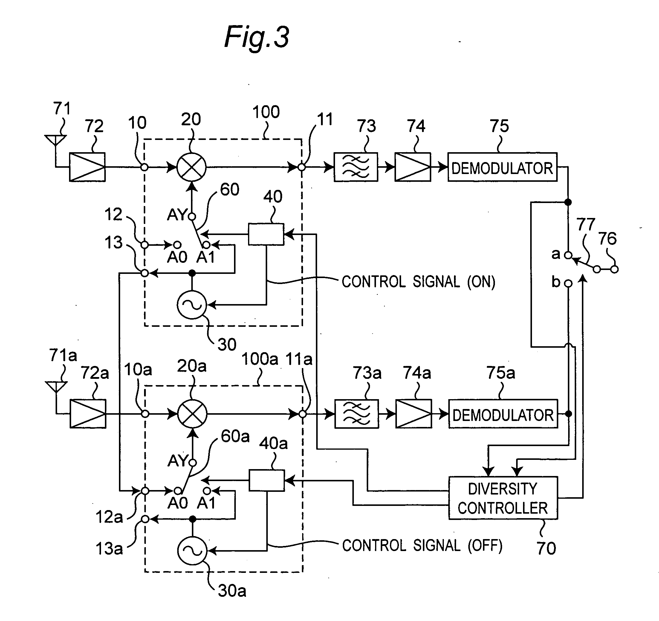
[0061]FIG. 3 is a block diagram showing a configuration of a diversity radio receiving apparatus according to a third preferred embodiment of the present invention. The diversity receiving apparatus shown in FIG. 3 is characterized by constituting the diversity receiving apparatus using two radio receiving apparatuses shown in FIG. 1. In this case, a frequency converter 100 and a frequency converter 100a have the same configuration as that of the frequency converter 100 shown in FIG. 1.
[0062] Referring to FIG. 3, the first radio receiving apparatus from an antenna 71 to a demodulator 75 is constituted in a manner similar to that of the radio receiving apparatus of FIG. 1. In addition, the second radio receiving apparatus from an antenna 71a to a demodulator 75a includes the antenna 71a, a high frequency amplifier 72a, a frequency converter 100a, a band-pass filter 73a, an intermediate frequency amplifier 74a, and the demodulator 75a, and it is constituted in a manner similar to tha...
PUM
 Abstract
Description
Claims
Application Information
 - R&D Engineer
- R&D Manager
- IP Professional
- Industry Leading Data Capabilities
- Powerful AI technology
- Patent DNA Extraction
Browse by: Latest US Patents, China's latest patents, Technical Efficacy Thesaurus, Application Domain, Technology Topic, Popular Technical Reports.
© 2024 PatSnap. All rights reserved.Legal|Privacy policy|Modern Slavery Act Transparency Statement|Sitemap|About US| Contact US: help@patsnap.com